
In my recent talk – A Short History of IoT – I discussed the various inventions, back in time, that led us to where we are with modern IoT.
I began with the Electric Telegraph as I believe it to be the first IoT Device. I explained some of the scientific discoveries which led to the invention of the Telegraph in a previous post.
To close out the talk, I finished with a show-stopper demo of a recreated Electronic Telegraph that I’d connected to an ESP8266 which would trigger a tweet to be sent with the decoded Morse Code Message.
This post details how I connected the ESP8266 to the Telegraph. In the next post I’ll dig in to how I then hooked the whole thing up to Azure and had it tweet out a message.
The Electric Telegraph
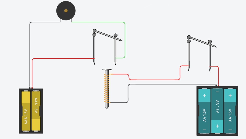
As part of the talk I created a Samuel Morse style Electric Telegraph;
This was a relatively straightforward build, in that there were only a few components;
Bringing the Telegraph into the 21st Century
As I was giving an IoT Talk, I wanted to bring the telegraph right up date. So, I decided to hook the Telegraph up to an ESP8266 so that I could decode the Morse Code Signals and squirt them out to the Terminal.
The Circuit
I modified my circuit to add the ESP8266;
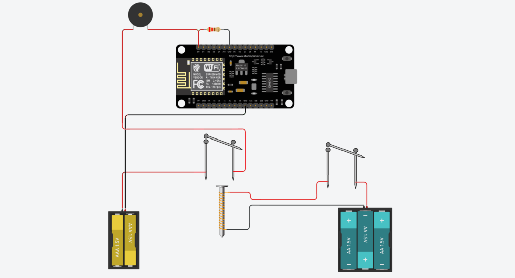
Here I’ve connected the positive end of the 3v Battery Pack through the Nail Receiver, onward through a Piezo Sounder and to the ESP8266 on input D0. I’ve pulled the input down to ground through a 220 Ohm resistor, as the circuit will pull the input up to a high value when activated.
The other side of the circuit is connected out through the GND pin the ESP8266 and back to the Battery pack’s negative terminal.
Arduino IDE Setup
Before you can get started with the ESP8266, you need to add the board to the Arduino IDE.
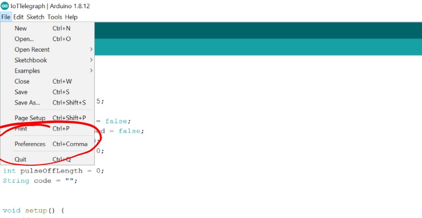
Open the Arduino IDE Preferences Dialog by clicking the Preferences Menu Item under File;
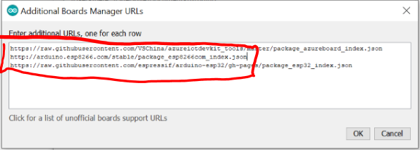
Once the Preferences Dialog is open, click on the Additional Board Manager URLs window button;
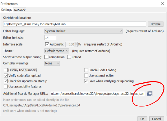
Add the following line to the Additional Board Manager URLs;
http://arduino.esp8266.com/stable/package_esp8266com_index.json
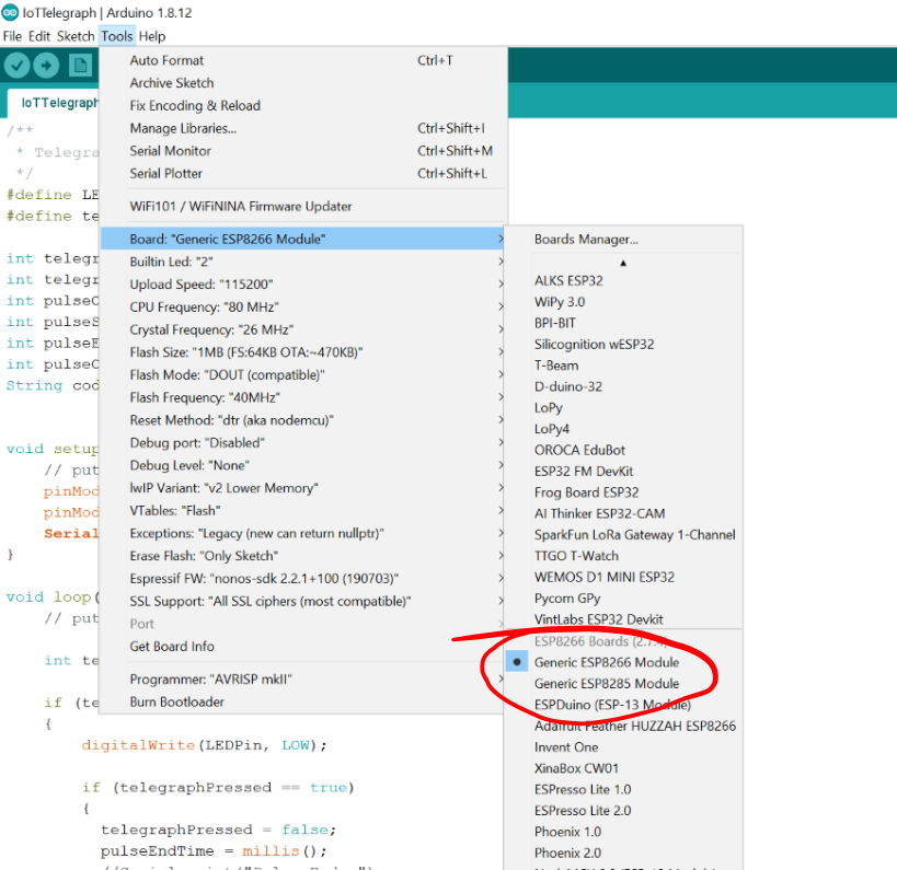
Next up, you can choose the “Generic ESP8266” option from the list of boards;
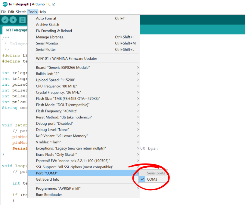
Finally, choose the correct COM port for your ESP8266;
The Basic Morse Decoding Software
I did some searching around and found a nice starting guide over on Instructables by Pinaki_91; https://www.instructables.com/id/Morse-Code-Decoder/
It needed some tidying up… It wasn’t working too well for the ESP8266, as it kept resetting the watchdog. It also didn’t have any decoding for numbers, so I fixed that up and I was good to go;
The basic operation is as follows;
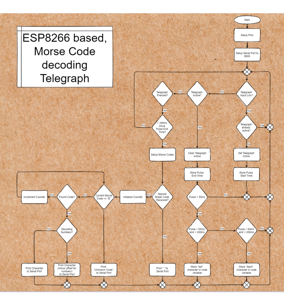
- If the Telegraph Input on D0 in pulled high by the Nail Circuit, then, so long as the telegraph pulse isn’t already being timed, then the current time (millis()) is stored in a variable. A flag is then set to true, indicating that the telegraph has been pressed and is being timed.
- If the Telegraph input is pulled low, then if the Telegraph was previously pressed, a second time is stored. These two times are subtracted and the difference stored in another variable.
- If the pulse length is less than 50ms, then it’s ignored completely as noise.
- If the pulse length is between 50 and 200ms, then it is treated as a dot. A single “.” is appended to a string which will be compared later.
- If the pulse length is between 200ms and 500ms, then it is treated as a dash. A single “-” is appended to the string.
- Anything longer than 500ms is ignored.
- If the telegraph input remains low (inactive) for a further 300ms, then it’s assumed that the end of a letter has been reached. The Converter routine is then called.
- The Converter routine simply compares the compiled string against and array of strings which map to each of the 26 letters, or each of the 10 numbers.
- The converter routine simply loops around until it finds the correct code. While looping an integer variable is incremented.
- If a matching code for a letter is found, then the integer value is added to the value of the ASCII “A”, which produces the correct ASCII letter. The Letter is then printed out to the serial port.
- If a matching code for a number is found, then the integer value is added to the value of the ASCII “A” minus a offset to produce the correct ASCII number. The Number is then printed out to the serial port.
- If no match is found, then an error message is printed to the serial port.
The Code
You can see the code right here in the GitHub repository;