Introduction
The Next Step
Continuing my series on Assembler for the SAM Coupé, where in the first post we introduced the various principles required to get started with Assembly Language Programming. We’ll now be looking at Graphics and Sprites and how to start showing Graphics on the screen.
If you haven’t caught up on the first post in this series, you can find the first post in the series here.
A New Sprite Editor
Since creating this post, I’ve created a really basic Sprite Editor that produces the required Sprite Data for this tutorial, so you can go on and show some far prettier sprites.
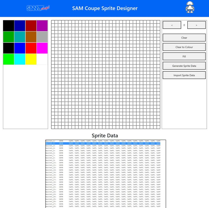
You can find the SAM Coupe Sprite Editor here;
https://www.petecodes.co.uk/sam-coupe-sprite-editor
It should be easy enough to get your head around… Just pick a colour, start clicking on pixels to create your Sprite. Then hit the Generate Sprite Data button.
At teh bottom of the page will be your Sprite Data.
Select all the text and copy that into your asm file (or over the top of the existing Sprite Data) and you’re good to go!
A Quick Word of Thanks
This has been quite a complicated blog post to write and get right, some of the topics needed a bit of research. It certainly wouldn’t of been possible without the help of the people in the Facebook SAM Coupe Users Group. Special mentions (in no particular order) go out to; Andrew Collier, Frode Tennebø, Graham Clemo, Stefan Drissen, Anton Javorček, Simon Owen, Colin Coupe, Adrian Brown and David Brown… Thanks all!
Introducing Graphics
What are sprites?
Wikipedia describes sprites as;
…a two-dimensional bitmap that is integrated into a larger scene.
In simple terms, a sprite is a small piece of graphics on the screen;

The main sprite in the above scene of course is our egg shaped friend Dizzy… In fact, there’s quite a few Sprites in the GIF above… The Cloud, the Spider, the Well, the Cauldron and so on…
In our example above, some of the sprites are changing their appearance, that is, to give the impression of movement, a series of different sprites are drawn one after another to provide animation. Nonetheless, each frame of the animation is made up of simply one sprite.
Introducing Graphics
What are sprites… Really?
Ok, so Sprites are actually just a collection of bytes of data relating to a set of individual pixels. Here’s an example of a simple sprite;
So, we have a white square filled with black… This could be viewed as series of 1’s and 0’s such as;
1, 1, 1, 1, 1, 1, 1, 1
1, 0, 0, 0, 0, 0, 0, 1
1, 0, 0, 0, 0, 0, 0, 1
1, 0, 0, 0, 0, 0, 0, 1
1, 0, 0, 0, 0, 0, 0, 1
1, 0, 0, 0, 0, 0, 0, 1
1, 0, 0, 0, 0, 0, 0, 1
1, 1, 1, 1, 1, 1, 1, 1
Where the 1’s will show a white pixel and the 0’s will show a black pixel. This is of course a simplifcation… The Sprite above is actually stored in memory as a series of bytes as follows;
DB &FF,&FF,&FF,&FF
DB &F0,&00,&00,&0F
DB &F0,&00,&00,&0F
DB &F0,&00,&00,&0F
DB &F0,&00,&00,&0F
DB &F0,&00,&00,&0F
DB &F0,&00,&00,&0F
DB &FF,&FF,&FF,&FF
You’ll see above, that there’s actually half as many columns of bytes above as you’d expect. This is because, to save space, the SAM combines columns of pixels into a single byte, with adjacent columns occupying adjacent nibbles (4 bits) of a byte. So, if we look again, at the second row down, we have;
DB &F0,&00,&00,&0FWe can see that the &F‘s correspond to our 1‘s and the &0‘s correspond to our 0‘s (as you’d expect). And you can see that the first byte is &F0, so we have a 1 and 0 pixel described in a single byte, with the opposite at the end where we have &0F, with a 0 and a 1 described in a single byte.
Introducing Graphics
The SAM Coupé Palette
To take things a little further, if we now consider the following sprite;
We now have a Green box with black centre…. The code for this sprite is;
DB &CC,&CC,&CC,&CC
DB &C0,&00,&00,&0C
DB &C0,&00,&00,&0C
DB &C0,&00,&00,&0C
DB &C0,&00,&00,&0C
DB &C0,&00,&00,&0C
DB &C0,&00,&00,&0C
DB &CC,&CC,&CC,&CC
So, we can now see that our &F‘s have changed to&C‘s. This is because the colour of each pixel is denoted by the value in each nibble of each byte. Each nibble can be set to one of 16 colours: 0 to F. The SAM Coupé however, actually has access to a total palette of 128 colours, but only 16 can be chosen at any one time. We’ll actually expand upon this somewhat later, where we’ll talk about Screen modes.
The main SAM Coupé Welcome Screen has a good example of the basic SAM Coupé Palette;
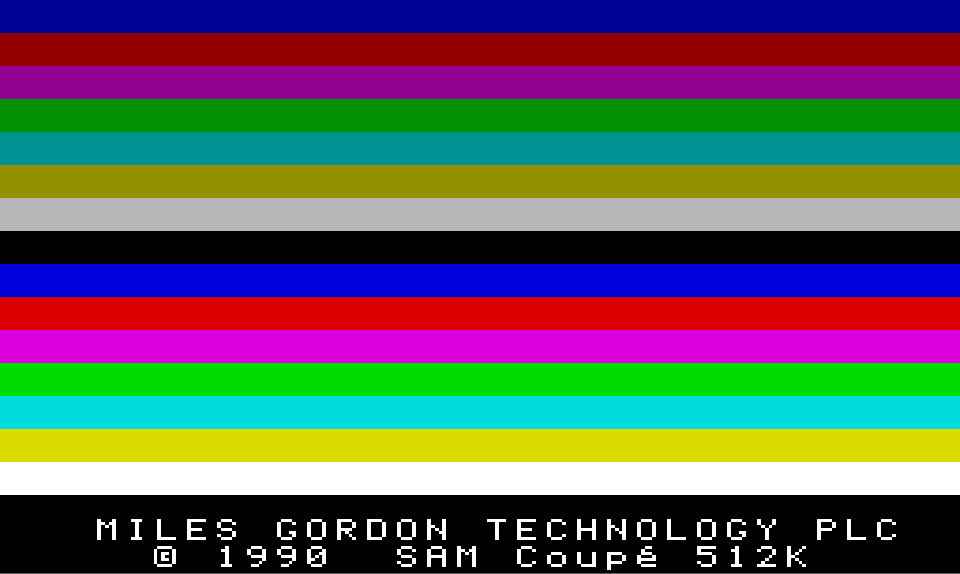
Each of the colours in the screen above is assigned to a number;

I’ve added the first black row here, as I guess MGT didn’t like a black bar at the top. You’ll see that colour 12 or C in HEX, is green and corresponds to the green in our sprite above.
These 16 colours are the default colours given to you when you first turn on your SAM… But, the SAM Coupé can actually choose from 128 colours in total. The full SAM Coupé Palette of 128 colours is shown below, with each colour’s associated number given beside it (Click to open the full image);
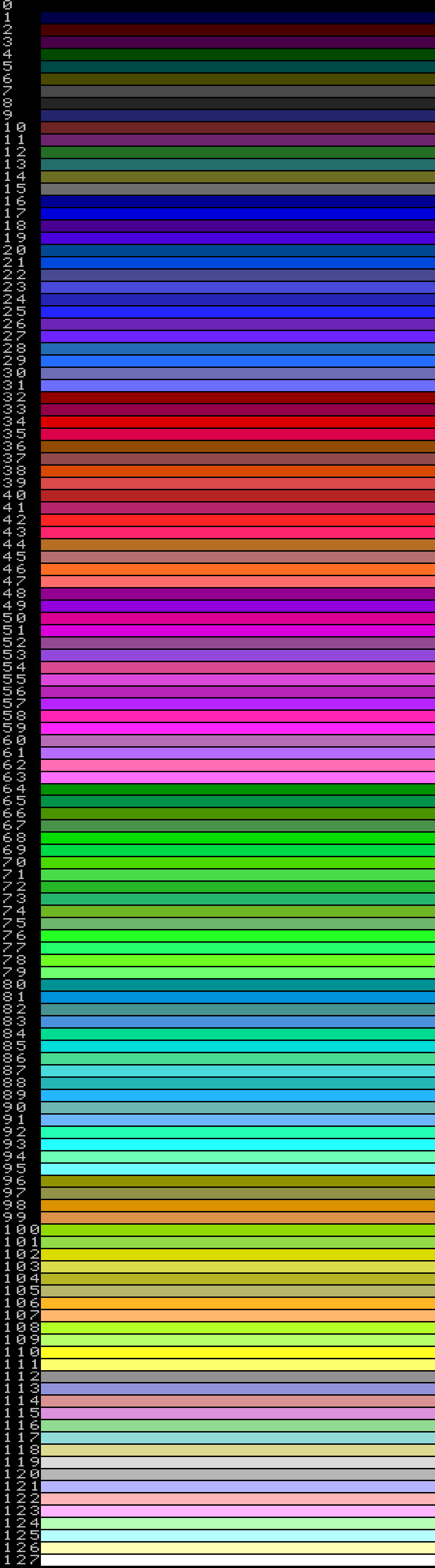
If you’d like to see the palette on your SAM Coupé, here’s a disk image which will automatically load the little palette test program from page 163 of the SAM Coupé User Manual.
We get to choose each of the 128 colours by using a technique called Palette Switching, which we’ll get onto later… It’s actually interesting to note that, although the SAM Coupé Welcome Screen looks straightforward enough, the Image is actually created using Palette Switching too rather than using a similair technique to the Palette Demo Program.
Introducing Graphics
The Screen Layout
The SAM Coupé has four different screen modes for different purposes, which are named Modes 1 to 4. They differ in the following ways as described in the SAM Coupé User’s Guide;
MODE 1
32 cells * 24 lines = 768 character cells, each cell has individual choice of PEN and PAPER colour.
256 * 192 pixels, choice of any 16 screen colours from 128.MODE 2
32 cells * 192 lines = 6,144 cells, each cell has individual choice of PEN and PAPER colour.
256 * 192 pixels, choice of any 16 screen colours from 128.MODE 3
512 pixels * 192 lines, each pixel has individual choice of colour, choice of any 4 screen colours from 128.
MODE 4
256 pixels * 192 lines, each pixel has individual choice of colour, choice of any 16 screen colours from 128.
It’s amusing to note that, the above section of the SAM Coupé User Guide (page 66) has an error, which states that that Mode 2’s 32×192 characters = 5,444 rather than the correct 6,144!
The default mode that the SAM Coupé starts in is Mode 4, and this is the mode we’ll be using in this guide.
Aside from Mode 3, you’ll notice that the SAM Coupé has a screen resolution of 256 pixels wide by 192 pixels high;
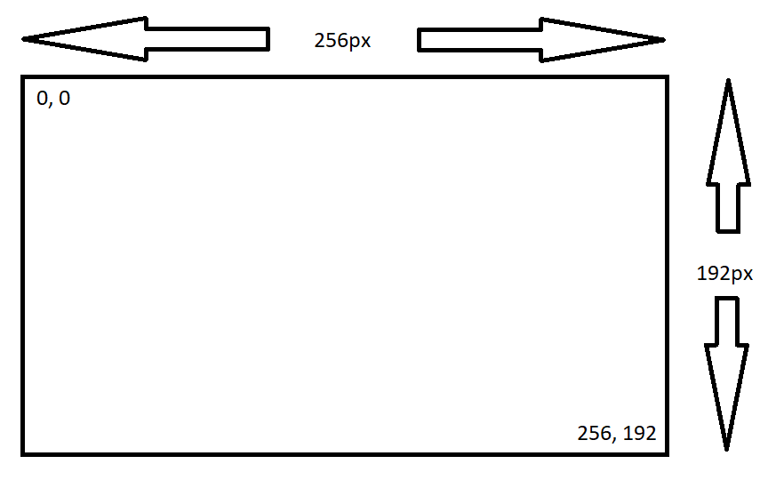
The origin, or the pixel at location 0 down by 0 across is in the top left-hand corner of the screen.
About Memory
The SAM Coupé Memory Map
Much like a lot of the 8 Bit computers from the 80’s and 90’s, the SAM Coupé uses a Z80B 8 Bit processor. To coordinate all of this MGT designed an ASIC, or Application Specific Integrated Circuit. The ASIC contains the control of the various SAM functions and Hardware… Everything from controlling the Display to controlling the on board MIDI ports.
The Z80B can only access 64 KB of Memory at any given time, which is in turn broken down into 4 banks of 16KB. This limitation of course is part an parcel of the Z80B being an 8 Bit Microprocessor, with a 16bit address space… Where, the maximum number which can be represented by 16 Bits is 65535 (or 65536 if you count 0).
But, we know of course, that the SAM Coupé has upto 512KB of RAM, so how does this 512KB translate to the 64KB addressable by the Z80B? One of the main functions of the ASIC is controlling how the Z80B communicates with the SAM Coupé’s Memory, both ROM (Read Only Memory) and RAM (Random Access Memory);
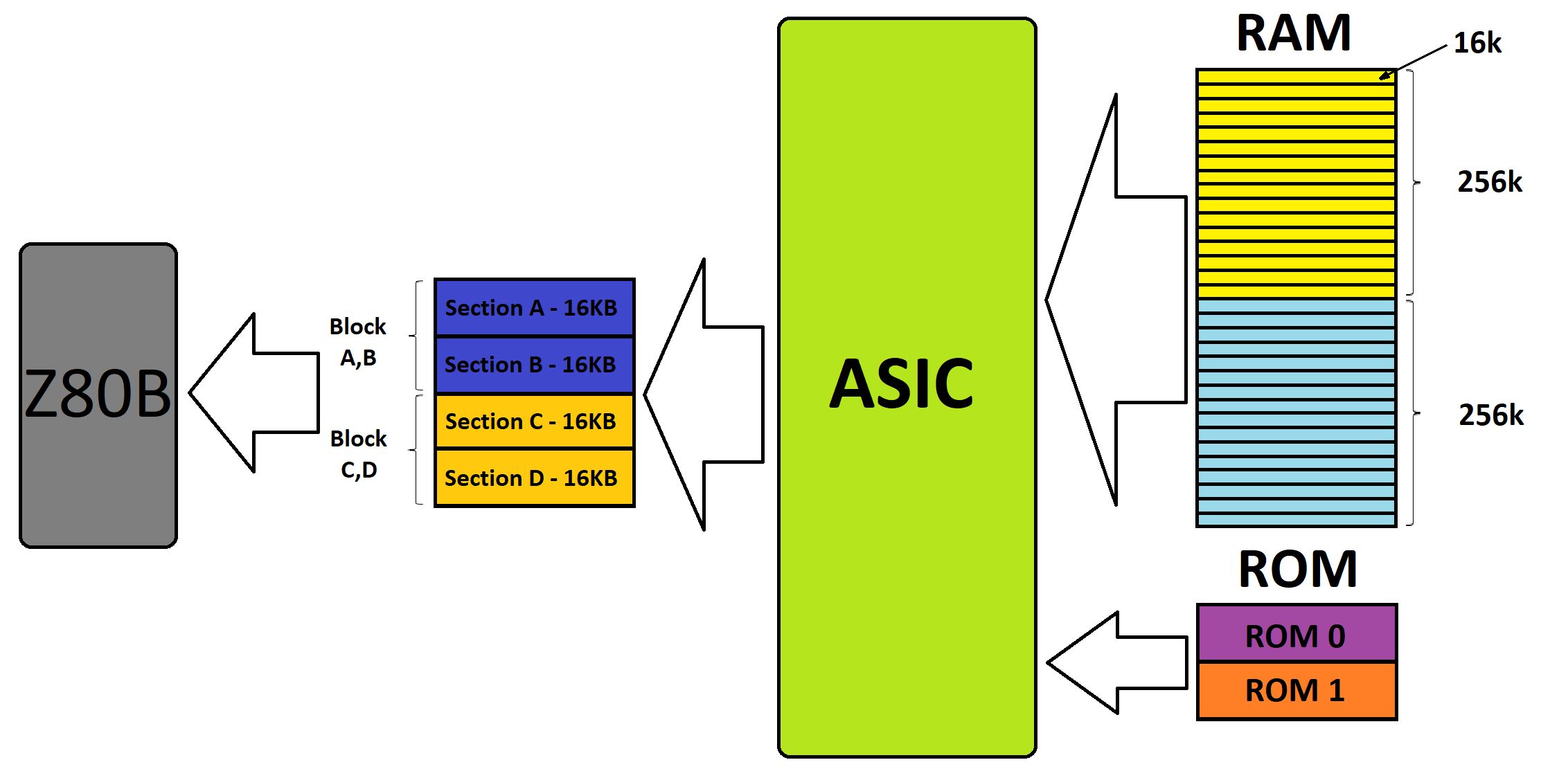
This is a simplified view of how things are connected together of course… But, we can work with this to help explain how things hang together.
About Memory
Paging
So, we know that the Z80B can only address up to 64KB of Memory, but we have up to 512KB to play with. Here’s where some of the magic of the SAM Coupé ASIC comes to life. In order to allow the Z80B to see our RAM (and ROM), that is, in order for the Z80B to execute instructions and process data held in our RAM, the ASIC “Pages” sections into the relevant positions in the 64KB address space that the Z80B can see it.
Wikipedia describes Memory Paging as;
…a memory management scheme by which a computer stores and retrieves data from secondary storage for use in main memory
Pretty obvious right? Well, in basic terms, the ASIC takes up to the full 512KB of the SAM Coupé’s RAM and splits it up into 32 Pages of 16KB. This then allows us to choose which sections of memory the Z80B can see at any one time. We choose which Pages the Z80B can see by using the LMPR and HMPR registers;
LMPR:
This register primarily controls which pages of RAM are paged into Sections A and B of the Z80B Memory space.
| Bit | Name | Function |
|---|---|---|
| 0 | BCD 1 | Low Memory Page Control |
| 1 | BCD 2 | Low Memory Page Control |
| 2 | BCD 4 | Low Memory Page Control |
| 3 | BCD 8 | Low Memory Page Control |
| 4 | BCD 16 | Low Memory Page Control |
| 5 | RAM0 | If set, ROM 0 is Paged out Section A of Memory and RAM paged in its place |
| 6 | RAM1 | If set, ROM 1 is Paged into Section D of Memory |
| 7 | WPRAM | If set, will write protect the RAM in Section A |
HMPR:
This register primarily controls which pages of RAM are paged into Sections C and D of the Z80B Memory space.
| Bit | Name | Function |
|---|---|---|
| 0 | BCD 1 | High Memory Page Control |
| 1 | BCD 2 | High Memory Page Control |
| 2 | BCD 4 | High Memory Page Control |
| 3 | BCD 8 | High Memory Page Control |
| 4 | BCD 16 | High Memory Page Control |
| 5 | MD3S0 | BCD 4 of the Mode 3 Colour Lookup Address |
| 6 | MD3S1 | BCD 8 of the Mode 3 Colour Lookup Address |
| 7 | MCNTRL | Set to Allow access to the External Memory Space |
 
About Memory
How Paging Works
If we look back at our simplified view of how the SAM Coupé Memory is organised, then we can see that the ASIC allows us, through the use of the LMPR, HMPR and VMPR registers, to allow the Z80 to read and write our RAM. The best way to imagine this is like a set of circuits perhaps, where we connect a wire between what the Z80B can read and write, and our RAM. So, imagine if we want to read and write the first four pages of our RAM… We’d need to tell the ASIC to page these into Sections A,B,C and D of the address space of the Z80B. Which is something like this graphically;
This actually works by setting the LMPR and HMPR registers up as follows;
LMPR:
| Bit | 7 | 6 | 5 | 4 | 3 | 2 | 1 | 0 |
|---|---|---|---|---|---|---|---|---|
| Value | 0 | 0 | 1 | 0 | 0 | 0 | 0 | 0 |
HMPR:
| Bit | 7 | 6 | 5 | 4 | 3 | 2 | 1 | 0 |
|---|---|---|---|---|---|---|---|---|
| Value | 0 | 0 | 0 | 0 | 0 | 0 | 1 | 0 |
You’ll notice in both cases that we only tell the ASIC to point to the first Page in memory… That is, we only tell the ASIC to put Page 0 in Section A and Page 2 in Section C. The ASIC will then take the next logical bank and page this automatically into the next section. So, we’ve put Page 0 into Section A and the ASIC automatically puts Page 1 into Section B. We put Page 1 into Section C and the ASIC automatically puts Page 3 into Section D.
About Memory
Screen Memory
So, we’ve explored how we go about reading and writing the SAM Coupé’s RAM (and ROM). If we’re going to put anything on the screen, then we’re going to need to write to the Screen Memory.
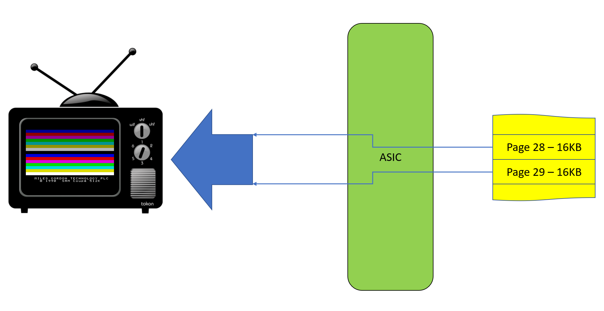
The SAM Coupé uses the VMPR register to let the ASIC know where it should look for the information to display on the Screen. It’s actually the SAM Coupé’s ASIC which deals with displaying data on the screen, and doesn’t involve the Z80B in this process at all.
The Screen Memory is slightly different to the regular RAM access, in that, for the ASIC to access the information to display on the screen, the ASIC simply needs to be instructed as to where in the full 512KB (or 256KB) the data resides. Once the VMPR is setup, the ASIC can continue to update the screen from the RAM without the need to use Paging to do so;
The VMPR register is as follows;
VMPR:
This register primarily controls which pages of RAM are Allocated to the Screen Memory.
| Bit | Name | Function |
|---|---|---|
| 0 | BCD 1 | Video Memory Page Control |
| 1 | BCD 2 | Video Memory Page Control |
| 2 | BCD 4 | Video Memory Page Control |
| 3 | BCD 8 | Video Memory Page Control |
| 4 | BCD 16 | Video Memory Page Control |
| 5 | MDEO | Screen Mode Control – Bit 1 |
| 6 | MDE1 | Screen Mode Control – Bit 2 |
| 7 | TXMIDI | MIDI Output Enable Bit |
| 7 | RXMIDI | MIDI IN Bit |
You can see from the table about that we only need to specify a single 16KB page of RAM where our screen is located. However, in Modes 3 and 4, the screen actually consumes 24KB of RAM. The ASIC handles this by automatically assigning the next page, the page directly after the one specified in the VMPR, as screen memory also.
It’s worth noting that the names of the modes follow the BASIC naming convention, i.e. Modes 1,2,3 and 4. However, to select Mode 1, we actually set the Mode Control Bits to 0 of course.
In Mode 4, if we wanted to use Pages 28 and 29 of RAM, as in the diagram above, as Screen Memory, we’d set the VMPR up as follows;
VMPR:
| Bit | 7 | 6 | 5 | 4 | 3 | 2 | 1 | 0 |
|---|---|---|---|---|---|---|---|---|
| Value | 0 | 1 | 1 | 1 | 1 | 1 | 0 | 0 |
So, we’ve set the Page Bits (Bits 0-4) to Point to Page 28, and the Page Mode Bits (Bits 5 & 6), as Page Mode 4.
When it comes time for us to actually modify the screen memory, we still need to page the relevant pages into the Z80B’s 64KB Address Space, just as with any other RAM operation, however as mentioned above, the ASIC automatically handles allowing the screen to be updated from the RAM directly.
A Basic Square Sprite
The Code
So, to get us going, let’s just get some really basic pixels drawn on the screen shall we…
Below is some basic code which will display a very simple square sprite like the following;
;
; -----------------------------------------------------------------------------------
; |                                                                                 |
; | Program:    SAM Coupe Sprites Tutorial 1 - Part 0                               |
; | Filename:   Sprites0.asm                                                        |
; | Version:    1.0                                                                 |
; | Date:       12/10/2017                                                          |
; | Author:     Pete Gallagher - PJG Creations Ltd                                  |
; |                                                                                 |
; -----------------------------------------------------------------------------------
;
                autoexec		; Automatically Execute the Program
		ORG 	32768		; Store the program in User Address Space
;
; Our Equates
;
LMPR:           EQU     250             ; The Lower Memory Page Register Address
HMPR:           EQU     251             ; The Higher Memory Page Register Address
VMPR:           EQU     252             ; The Video Memory Page Register Address
;
; Get the Current Screen Page and set the LMPR register up so we can write to the screen
;
                IN      A,(VMPR)        ; Get the VMPR Register, which holds info about...
                                        ; ... which Page the Screen is Paged Into
                AND     0B00011110      ; We're only interested in the Screen Page, so mask off everything but the Page Bits...
                                        ; ... The result will be stored in the A Register
                OR      0B00100000      ; Set Bit 5 which, when loaded into the LMPR register, will Set the RAM in Page 0
                OUT     (LMPR),A        ;
;
; Print a sprite in the top left corner
;
                LD      HL,0x0000       ; Point to the Top Left corner of our screen
                LD      (HL),0xFF       ; Set the colour of this pixel

                LD      HL,0x0080       ;
                LD      (HL),0x44       ; Set the colour of this pixel

                LD      HL,0x0001       ;
                LD      (HL),0xFF       ; Set the colour of this pixel

                LD      HL,0x0081       ;
                LD      (HL),0x44       ; Set the colour of this pixel

                LD      HL,0x0100       ;
                LD      (HL),0xFF       ; Set the colour of this pixel

                LD      HL,0x0180       ;
                LD      (HL),0x44       ; Set the colour of this pixel

                LD      HL,0x0101       ;
                LD      (HL),0xFF       ; Set the colour of this pixel

                LD      HL,0x0181       ;
                LD      (HL),0x44       ; Set the colour of this pixel
;
; We must remember to switch BASIC back into Page 0
;
                LD      A,0x1f          ;
                OUT     (LMPR), A       ;
;
; Exit back to BASIC
;
                RET                     ;
You can download a disk Image of the above code here.
A Basic Square Sprite
Understanding the Code
Setup and Equates:
As in the previous tutorial, we need to tell the Assembler where to put our code in the SAM Coupé RAM, and we also would like our code to Automatically Execute. We set this up on lines 12 and 13;
autoexec
ORG 32768
Next we make our lives slightly easier when dealing with the LMPR, HMPR and VMPR, by creating what’s known as an equate. This basically replaces a number with a nice friendly label. So we have the following at lines 17 to 19;
LMPR: EQU 250
HMPR: EQU 251
VMPR: EQU 252
Where 250 is the address of the LMPR, 251 is the HMPR and 252 is the VMPR.
Getting the Screen RAM location:
As explained above, The SAM Coupé can read and display the information from RAM, however if we want to write to the Screen Data, we need to page this into the Z80B address space.
The SAM Coupé starts up with the VMPR setup to point to Pages 30 and 31. But, to write reusuable code, we need to actually find the page of RAM that the VMPR is pointing to, and load this address into our LMPR so that we can write to it. The section on lines 23 to 28 achieve just this;
IN   A,(VMPR)
AND  0B00011110
OR   0B00100000
OUT  (LMPR),A
First, we grab the current location of Screen Memory from the VMPR using indirect addressing (denoted by the brackets).
Next we use an AND statement to remove everything except for the Screen Page bits (bits 0-4)… We also ignore bit 0, as the Screen Memory is only loaded in at even locations, as if we’re in Modes 3 or 4, then the ASIC will automatically assign the subsequent page to fulfil the 24KB requirement mentioned above.
After this we set bit 5 of the A register, which when loaded into the LMPR register, will page the ROM our of Page 0, and page RAM in in its place.
Finally, we load our A register into our LMPR, once again using indirect addressing.
Writing to the screen:
Ok, so now we’ve got the screen memory paged into the Z80B’s address space, and we’re ready to start writing some information to display!
With our Screen Memory paged into Sections A & B, then the top left hand corner of the screen will be at address 0. So, on line 32, we set the HL register pair up to point to address 0;
LD HL,0x0000With the HL register pair set up, we can now write our first pixel to screen memory. In actual fact, we’ll be writing two pixels at once, as explained in the “Introducing Graphics – The SAM Coupé Palette” section above.
In order to maximise the RAM usage, each Screen Memory location is split into two halves, with adjacent pixels occupying the Upper and Lower Nibbles of each Byte. Working from Left to Right, the Upper Nibble of a Byte (bits 4-7), represent the left most pixel at a location, and the Lower Nibble (bits 0-3), represent the right most pixel at a location.
So, on line 33, we load a value of 0xFF into the location Pointed to by the HL register – Address 0 or the top left corner of our screen. This in turn sets the pixel at location 0,0 (row 0, line 0) to White, aswell as the pixel at location 1,0 (row 1, line 0);
LD (HL),0xFFThis should have the effect of drawing two white pixels at the top left corner of the screen.
Next we want to draw to green pixels directly below our two white pixels. We know from the specifications that the SAM Coupé Screen (in mode 4), is 256 pixels wide. So, each line is 256 Pixels long. So, in order to write a pixel on the second line down, we simply need to add 256 (0x80 in HEX) to the value in our HL register pair, and we move a line down. We can see this on line 35;
LD HL,0x0080We’re now pointing at 0,1 (row 0, line 1), directly under our first two white pixels. As explained above, the colour information of our pixels is denoted by the value loaded into each nibble of the Screen Memory Bytes. We used 0xF to print a white pixel, we’ll now write a green pixel on line 36, so we can see the difference between each line;
LD (HL),0x44We then repeat this action 4 more times on lines 38 to 54, writing two pixels at a time on alternate lines until we complete our first sprite.
Returning us safely to BASIC:
Before our program exits, it’s always a good idea to return the ROM back to Sections A and B, as BASIC requires this when we return to it. We accomplish this on lines 58 & 59, by simply writing a value of 0x1F back to our LMPR, which pages in the RAM at page 31, as well as clearing the bit which returns ROM0 to Section A;
LD  A,0x1f
OUT (LMPR), A
Finally, we return back to BASIC using the RET command on line 63, which exits our program, returning us to the friendly home comforts of BASIC.
A Basic Square Sprite
Slowing the process down
To give you a better idea of how the sprite is drawn onto the screen, we can add a routine between each pixel such that the process will wait for the user to press a key;
;
; -----------------------------------------------------------------------------------
; |                                                                                 |
; | Program:    SAM Coupe Sprites Tutorial 1 - Part 1                               |
; | Filename:   Sprites1.asm                                                        |
; | Version:    1.0                                                                 |
; | Date:       12/10/2017                                                          |
; | Author:     Pete Gallagher - PJG Creations Ltd                                  |
; |                                                                                 |
; -----------------------------------------------------------------------------------
;
		autoexec		; Automatically Execute the Program
		ORG 	0x8000		; Store the program in User Address Space
;
; ***********************************************************************************
; *                                                                                 *
; *                                    Equates                                      *
; *                                                                                 *
; ***********************************************************************************
;
LMPR:           EQU     250             ; The Lower Memory Page Register Address
HMPR:           EQU     251             ; The Higher Memory Page Register Address
VMPR:           EQU     252             ; The Video Memory Page Register Address
JCLSBL:         EQU     334             ; The Clear Screen Routine (Set A to 0 to clear the whole screen) (0x14E)
;
; ***********************************************************************************
; *                                                                                 *
; *                                Application Start                                *
; *                                                                                 *
; ***********************************************************************************
;
                CALL    Clear_Screen    ;
;
; Get the Current Screen Page and set the LMPR register up so we can write to the screen
;
                IN      A,(VMPR)        ; Get the VMPR Register, which holds info about...
                                        ; ... which Page the Screen is Paged Into
                AND     0B00011110      ; We're only interested in the Screen Page, so mask off everything but the Page Bits...
                                        ; ... The result will be stored in the A Register
                OR      0B00100000      ; Set Bit 5 which, when loaded into the LMPR register, will Set the RAM in Page 0
                OUT     (LMPR),A        ;
;
                CALL    Wait_For_Key    ;
;
; Print a sprite in the top left corner
;
                LD      HL,0x0000       ; Point to the Top Left corner of our screen
                LD      (HL),0xFF       ; Set the colour of pixels 0,0 and 0,1 to White
                CALL    Wait_For_Key    ;
                LD      HL,0x0080       ;
                LD      (HL),0x44       ; Set the colour of pixels 1,0 and 1,1 to Green
                CALL    Wait_For_Key    ;
                LD      HL,0x0001       ;
                LD      (HL),0xFF       ; Set the colour of pixels 0,2 and 0,3 to White
                CALL    Wait_For_Key    ;
                LD      HL,0x0081       ;
                LD      (HL),0x44       ; Set the colour of pixels 1,2 and 1,3 to Green
                CALL    Wait_For_Key    ;
                LD      HL,0x0100       ;
                LD      (HL),0xFF       ; Set the colour of pixels 1,0 and 1,1 to White
                CALL    Wait_For_Key    ;
                LD      HL,0x0180       ;
                LD      (HL),0x44       ; Set the colour of pixels 2,0 and 2,1 to Green
                CALL    Wait_For_Key    ;
                LD      HL,0x0101       ;
                LD      (HL),0xFF       ; Set the colour of pixels 1,2 and 1,3 to White
                CALL    Wait_For_Key    ;
                LD      HL,0x0181       ;
                LD      (HL),0x44       ; Set the colour of pixels 2,2 and 2,3 to Green
                CALL    Wait_For_Key    ;
;
; We must remember to switch BASIC back into Page 0
;
                LD      A,0x1F          ;
                OUT     (LMPR), A       ;
;
; Exit back to BASIC
;
                RET                     ;
;
; ***********************************************************************************
; *                                                                                 *
; *                                Clear the Screen                                 *
; *                                                                                 *
; ***********************************************************************************
;
Clear_Screen:   LD      A,0             ;
                CALL    JCLSBL          ;
                RET
;
; ***********************************************************************************
; *                                                                                 *
; *                                Wait for a KeyPres                               *
; *                                                                                 *
; ***********************************************************************************
;
Wait_For_Key:   IN      A, (LMPR)       ;
                RES     5, A            ;
                SET     0, A            ;
                OUT     (LMPR),A
;
Key_Loop:       CALL	&0169		; Read the Keyboard (Zero if no key)
       		JR 	Z,Key_Loop      ; If no key pressed, then loop
;
No_Key_Loop:    CALL	&0169		; Read the Keyboard (Zero if no key)
       		JR 	NZ,No_Key_Loop  ; If key still pressed, then loop

                IN      A,(LMPR)        ;
                SET     5, A            ;
                RES     0, A            ;
                OUT     (LMPR),A
;
                RET                     ;
The Clear Screen ROM Routine:
Most of the first section of our new Part 1 code above is the same as in Part 0, until we get to lines 24 and 32 where we’re defined an equate for the JCLSBL Clear Screen ROM Routine on line 24;
EQU 334We then call a little subroutine of our own on line 32 which sets up the A Register and calls the ROM routine.
The JCLSBL routine either clears the whole screen, if the A register is 0, or just the lower part of the screen if the A register isn’t 0. It’s counterpart JCLSLOWER clears the bottom half of the screen.
This routine forms a set of ROM routines which include, but are not limited to;
- JMODE – Set the Screen mode stored in the A register
- JKBFLUSH – Clear the Keyboard Buffer
- JREADKEY – Read a key from the Keyboard Buffer – We used this routine in the previous tutorial if you remember!
- JWAITKEY – Wait for a key to be pressed
Waiting for a key and ROM Paging:
On line 43 we have the first call to our Wait_For_Key routine, which is down there on lines 112 to 128. You’ll notice however, that this version of the routine however differs slightly from the version we used in the previous tutorial, where we’re now have the following setup before we wait for a key;
IN A, (LMPR)
RES 5, A
SET 0, A
OUT (LMPR), A
What we’re doing here is restoring ROM0 to Section A of the Z80B’s Address Space. If you remember from the previous program, we need to actually page ROM0 out of Section A, and page our Screen Memory in RAM in it’s place, which we do in this program on lines 36 to 41. However, that means that our ROM routines aren’t there to be called while we’re updating the screen.
As such, what we need to do is page ROM0 back into the Z80B address space, so we can call our JREADKEY Rom routine. We then wait for the user to press and release a key, after which we reverse the process, and page the screen memory back into Section A so we can continue to update the screen afterwards.
The rest of our program is exactly the same as the previous version, and with each key press, you’ll see our simple sprite be built up;
And you can download a disk image of our program right here.
A Basic Square Sprite
What are those weird pixels?
If you’ve ran the previous program, the eagle eyed among you may have noticed some strange pixels appear on the screen after each press of a key;
We’ve already mentioned above that in order to write to the screen memory, we needed to page the allocated area of RAM into the Z80B’s address space. Likewise, in order to call any of the SAM Coupé ROM routines, we need to page the ROM back into the Z80B address space.
As well as the ROM, there are a few other things located in the Z80B address space that we need to take care of, one of which is causing our mysterious pixels…
The Z80B Stack:
Wikipedia describes the Stack as an abstract area of memory which;
…stores information about the active subroutines of a computer program
In simple terms, whenever we use the CALL instruction to call a subroutine, the Z80B stores the address that it needs to return to on the Stack, so that when it encounters the subsequent RETurn instruction it knows where to return to in memory.
You can think of the Stack as a physical stack of plates;

The Stack follows a principle known as LIFO, or Last In First Out. As illustrated in the animation above, the Z80B puts each return address on the Stack one on-top of each other, and then takes the very first one off the top when it encounters a RETurn instruction. This ensures that the address pulled off the top first, was the last location in memory to return to.
By default (that is at startup), the SAM Coupé stores its Stack area at address 4EF2 in the Z80 Address Space, we can see this if we show the debugger when SimCoupe starts up;
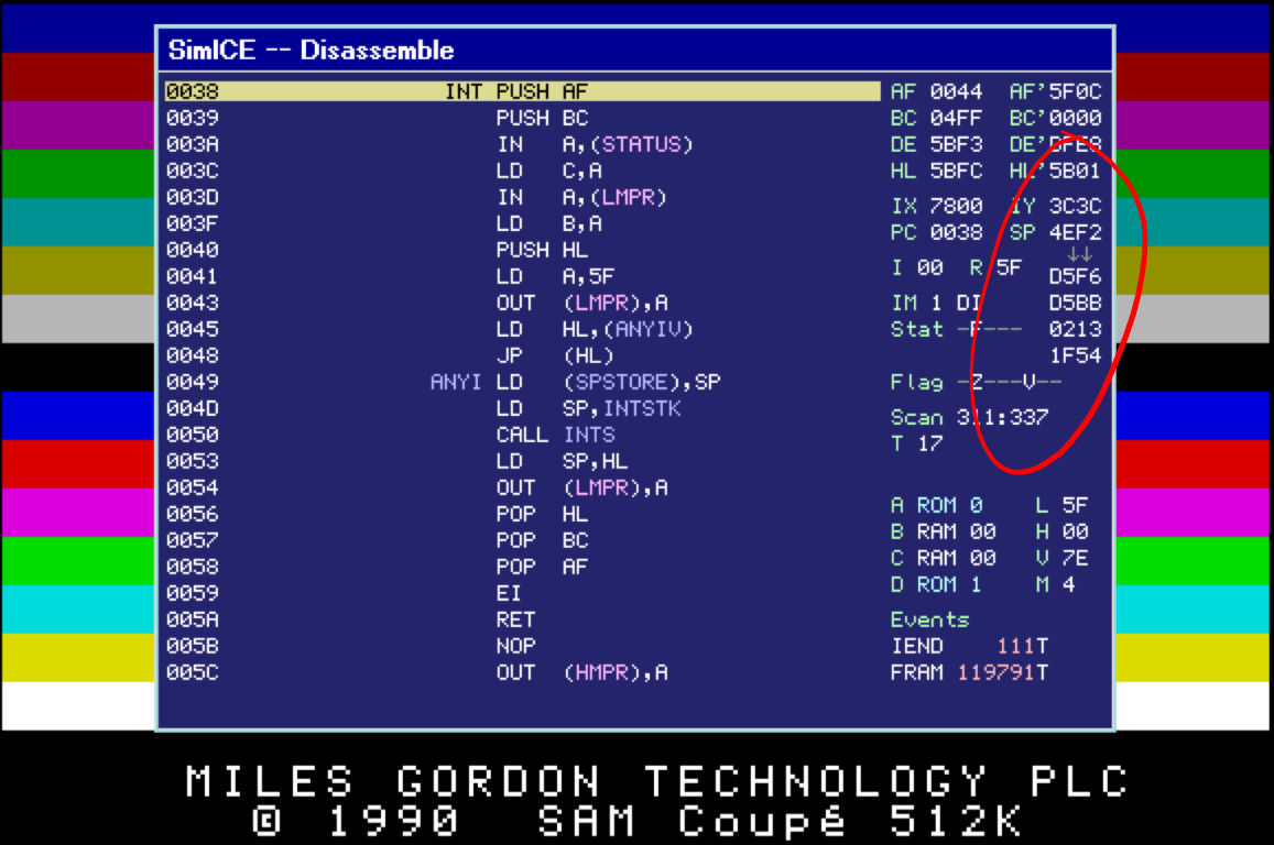
So we can see here that SimCoupe is telling us that the Stack is located at 4EF2, and that the first item on the Stack is the address D5F6. If we look at what’s at this address in memory;
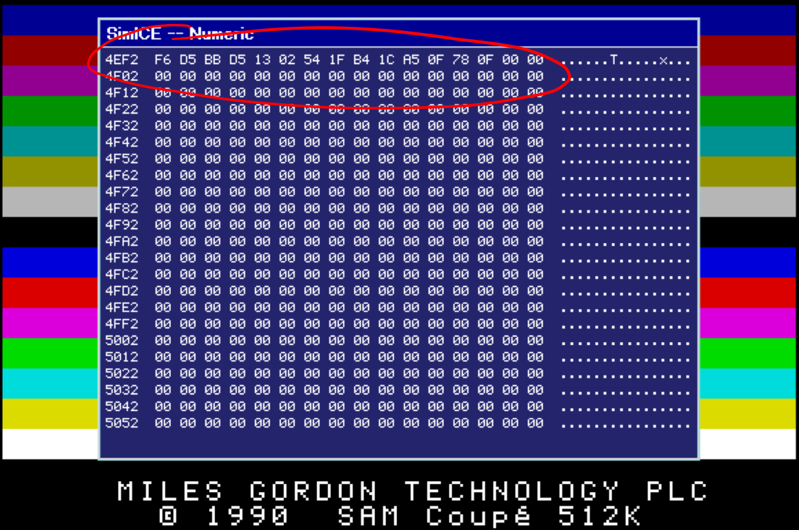
We can see that we have the contents of the Stack, albeit not to forget that addresses are stored Low byte then High Byte of course.
A Basic Square Sprite
So what’s actually happening?
If we watch a run through of our code through the debugger it becomes clear what’s actually happening;
We can see our call to the Clear_Screen routine adds the next execution address of 0x8003 to the Stack, and pulls that value back from the stack once it hits the RETurn statement.
We then see, as the execution progresses and we page our Screen Memory in the Z80B address space, the Stack is cleared down to zero’s. Obviously, at this point, we’re now set up to write to our screen memory.
If we continue on, you can see we then make a call to our Wait_For_Key routine. As a result, the Z80B stores the address of the next instruction on the Stack, address 0x800E. It’s at this point that things aren’t quite right. If we look again, the Stack is still located at 0x4EF6.
As explained previously, in Mode 4, The Screen Memory isn’t a nice neat 16KB (0x4000 in HEX) it’s actually 24KB in length (0x6000 in HEX), which means that, as we’ve paged our Screen into the Z80B address space, the screen will span from 0x0000 all the way to 0x6000.
This means that when the Z80B writes to the Stack, it’s actually writing to address 0x4EF6 which is towards the bottom of the screen memory! As a result, we get strange pixels appearing near the bottom of our screen.
A Basic Square Sprite
A little about Interrupts
Wikipedia describes an interrupt as;
a signal to the processor emitted by hardware or software indicating an event that needs immediate attention.
In simple terms… For the SAM Coupé to function in a way that allows a user to interact with it while still executing programs, it must perform certain tasks at regular intervals. These tasks include such things as;
- Checking if a key has been pressed
- Checking if the Mouse has moved
- Actioning any MIDI data
- Updating the screen
The SAM Coupé achieves this by leaving the executing program and checking in on these items at regular intervals. This is process is called “interrupting”, and to perform this process, the Z80B will jump to the relevant section of code for the item to check, perform the necessary checks, and RETurn to the place in the program it was at before Interrupting.
When the Z80B performs an interrupt it saves the address to which it needs to RETurn to on the Stack, just like a CALL to a subroutine, and will obviously have the same effect to boot.
A Basic Square Sprite
How do we cure those weird pixels then?
The SAM Coupé Z80B Stack Pointer, shown as SP in the debugger, is actually a 16bit register pair similair to the HL register pair. This register points to a location in memory where the Stack is actually located in memory. As such, we can actually move the Stack location by loading a location of our choosing into the SP register.
With this in mind we have the following new version of our program;
;
; -----------------------------------------------------------------------------------
; |                                                                                 |
; | Program:    SAM Coupe Sprites Tutorial 1 - Part 2                               |
; | Filename:   Sprites1_2.asm                                                      |
; | Version:    1.2                                                                 |
; | Date:       12/10/2017                                                          |
; | Author:     Pete Gallagher - PJG Creations Ltd                                  |
; |                                                                                 |
; -----------------------------------------------------------------------------------
;
		autoexec		; Automatically Execute the Program
		ORG 	0x8000		; Store the program in User Address Space
                DUMP	1,0             ; Store the Program in Page 1 (B)
;
; ***********************************************************************************
; *                                                                                 *
; *                                    Equates                                      *
; *                                                                                 *
; ***********************************************************************************
;
LMPR:           EQU     250             ; The Lower Memory Page Register Address
HMPR:           EQU     251             ; The Higher Memory Page Register Address
VMPR:           EQU     252             ; The Video Memory Page Register Address
JCLSBL:         EQU     334             ; The Clear Screen Routine...
                                        ; ... Set A to 0 to clear the whole screen) (0x14E)
JREADKEY:       EQU     361             ; The Keyboard Read Routine...
                                        ; ... Returns with Z Flag set if no key pressed...
                                        ; ... Otherwise A = Keycode for key pressed
;
; ***********************************************************************************
; *                                                                                 *
; *                                Application Start                                *
; *                                                                                 *
; ***********************************************************************************
;
                DI                      ; Disable Interupts
;
; Becuase the Stack Pointer lives in Page B, but we're paging the Screen into Pages A and B,
; we need to make sure we save the current Stack Pointer location, and create our own location.
; We rewrite our program here effectively, by storing it's original location in a holding position.
;
                LD	(System_SP+1),SP; Get the Current Stack Pointer Location and Overwrite...
                                        ; ... the holding value below.
;
; Get the Current Screen Page and set the LMPR register up so we can write to the screen
;
                IN      A,(VMPR)        ; Get the VMPR Register, which holds info about...
                                        ; ... which Page the Screen is Paged Into
                AND     0b00011110      ; We're only interested in the Screen Page...
                                        ; ... so mask off everything but the Page Bits...
                                        ; ... The result will be stored in the A Register
                OR      0b00100000      ; Set Bit 5 which, when loaded into the LMPR register...
                                        ; ... will Set the RAM in Page 0
                LD	(Scr_Page+1),A  ; Overwrite the holding value for the Screen Page location...
                                        ; ... now that we know it
;
                CALL    Clear_Screen    ; Clear the Screen
;
                LD	SP,0xC000       ; Set the Stack Pointer to a location of our choosing
;
                LD	A,(Scr_Page+1)  ; Get the current Screen Location which we stored earlier
;
		OUT     (LMPR),A        ;
;
; All of the above shifting around of the Stack Pointer, allows us to Call routines...
; ... Which of course will store their return location on the Stack Pointer...
; ... This would've overwritten some of the Screen Page if left unreseolved...
;
                CALL    Wait_For_Key    ; Wait for a keypress
;
; Print a sprite in the top left corner
;
                LD      HL,0x0000       ; Point to the Top Left corner of our screen
                LD      (HL),0xFF       ; Set the colour of pixels 0,0 and 0,1 to White
                CALL    Wait_For_Key    ; Wait for a keypress
                LD      HL,0x0080       ;
                LD      (HL),0x44       ; Set the colour of pixels 1,0 and 1,1 to Green
                CALL    Wait_For_Key    ; Wait for a keypress
                LD      HL,0x0001       ;
                LD      (HL),0xFF       ; Set the colour of pixels 0,2 and 0,3 to White
                CALL    Wait_For_Key    ; Wait for a keypress
                LD      HL,0x0081       ;
                LD      (HL),0x44       ; Set the colour of pixels 1,2 and 1,3 to Green
                CALL    Wait_For_Key    ; Wait for a keypress
                LD      HL,0x0100       ;
                LD      (HL),0xFF       ; Set the colour of pixels 1,0 and 1,1 to White
                CALL    Wait_For_Key    ; Wait for a keypress
                LD      HL,0x0180       ;
                LD      (HL),0x44       ; Set the colour of pixels 2,0 and 2,1 to Green
                CALL    Wait_For_Key    ; Wait for a keypress
                LD      HL,0x0101       ;
                LD      (HL),0xFF       ; Set the colour of pixels 1,2 and 1,3 to White
                CALL    Wait_For_Key    ; Wait for a keypress
                LD      HL,0x0181       ;
                LD      (HL),0x44       ; Set the colour of pixels 2,2 and 2,3 to Green
                CALL    Wait_For_Key    ; Wait for a keypress
;
; We must remember to switch BASIC back into Page 0
;
                LD      A,0x1F          ; Set ROM0 back into Page A...
                OUT     (LMPR), A       ; ... So that when we try to return to BASIC it all still works!
;
; Return the System Stack Pointer to it's original location in Bank B somewhere...
;
System_SP:	LD      SP,0            ; Place holder for the System Stack Location...
                                        ; This will be overwritten above once we know it's location
                EI                      ; Enable Interupts
;
; Return back to BASIC
;
                RET                     ;
;
; ***********************************************************************************
; *                                                                                 *
; *                                Clear the Screen                                 *
; *                                                                                 *
; ***********************************************************************************
;
Clear_Screen:   XOR     A               ; Clear the A register, so when passed into clear screen...
                                        ; ...it clears the whole screen
                CALL    JCLSBL          ; Clear the Screen
                DI                      ; Disable Interupts
                RET                     ;
;
; ***********************************************************************************
; *                                                                                 *
; *                                Wait for a KeyPres                               *
; *                                                                                 *
; ***********************************************************************************
;
Wait_For_Key:   LD	A,0x1F          ; Set for ROM in Page A
                OUT 	(LMPR),A        ;
;
Key_Loop:       CALL	JREADKEY	; Read the Keyboard (Zero if no key)
       		JR 	Z,Key_Loop      ; If no key pressed, then loop
;
No_Key_Loop:    CALL	JREADKEY	; Read the Keyboard (Zero if no key)
       		JR 	NZ,No_Key_Loop  ; If key still pressed, then loop
;
                DI                      ; Disable Interuprts
;
Scr_Page:	LD      A,0	        ; Place holder for the Screen Page...
                                        ; ...The 0 will be overwritten above once we know where it is...
                OUT	(LMPR),A        ; Page the Screen into the relevant Page
                RET                     ;
Other than a few minor setup differences which don’t affect how our program works, but do ensure that it is loaded into memory using the correct sequence, our program is identical until line 37, where we use the DI instruction to Disable Interrupts. This command simply prevents the Z80B from actioning any of the interrupt requests it receives when we’re not ready for them. This prevents any modifications of our RAM as a result of code running which we don’t have control over, thus preventing screen corruption amongst other things.
Self Modifying Code:
The next change we have is at line 43, where we employ a new technique to save the current address of the Stack (i.e. the current value held in the SP register). Here we’re using a technique called Self Modifying Code, in order to change the value of a part of our program;
LD (System_SP+1),SPAt line 122, we have a line labelled System_SP, with the following instruction;
LD SP,0Our line at 43, takes the value of the Stack Pointer, and writes it (using indirect addressing) into the address of System_SP+1. This equates to the position of the 0 on line 122, and as such means that we write the value held in the SP register directly over the initial 0.
The reason we do this is so that, later on, when we exit back out of our program, we can restore the location of the original Stack, as BASIC may need the return addresses for it’s own purposes.
Our code remains the same again until we reach line 56, where once again we employ Self Modifying Code to slim down how we return from the Wait_For_Key routine;
LD (Scr_Page+1),AThis line modifies the value held at line 159 where we have the following line of code with the label Scr_Page;
LD A,0Here we’re effectively overwriting the 0 with the address of our screen memory which we ascertained on lines 48 to 53 as we always have. This saves us having to setup the LMPR register to point to our screen memory, and save us three lines of code and a few clock cycles in the process.
You’ll also notice that we Disable the Interrupts again when we’re exiting the Wait_For_Key routine. This is because a call to the ROM routines may automatically re-enable interrupts, which could obviously cause us problems, so to be safe, we make sure that interrupts are disabled once again.
Moving the Stack Pointer:
On line 59 we once again call our little routine to Clear the Screen. Bearing in mind that we’re calling ROM here, so we’ve not yet paged the ROM out of memory and replaced it with our Screen Memory.
Then, on line 61 we have the following line;
LD SP,0xC000Here is where we move the location of the Stack to somewhere where we know it’s not going to have an impact upon our Screen Operations. We choose 0xC000 as it’s outside of the 0 to 0x6000 address range our Screen Memory occupies when Paged into Sections A and B.
Next we grab the location of our Screen Memory, and page it into the Z80B address space ready for writing, just as we’ve done before.
Our code then remains identical until we get to line 122 where, as explained earlier, we now restore the location of the Stack to its original location, so that BASIC can continue to use it unabated.
We also re-enable Interrupts before returning to BASIC, so the SAM Coupé can continue running normally.
A small improvement:
When considering Assembly Language Programming, one of the major benefits is the speed at which programs are executed, primarily because we’re talking the language of the processor, so our program doesn’t have to be interpreted before it’s run, making it way faster than BASIC for instance.
However, just because our program is a lot faster, doesn’t mean that we should ignore any efficiency gains we can make by carefully choosing which instructions to use for a given task.
Each instruction takes a certain number of Clock Cycles, which are known as T-States, to execute, and the less T-States we use up the quicker our program will run. We have made an efficiency improvement within our Clear_Screen routine on line 136… Where in our original program we cleared the A register by loading it with a 0;
LD A,0This instruction takes 7 T-States to execute. You’ll notice that in the new version of our program we now use;
XOR AThis instruction only takes 4 T-States, so a saving of 3 T-States… I know, it’s not a massive amount… But, if this were a large program, and we were using this routine many many times every time we wanted to update the screen, then this saving would really start to add up.
Once again, you can download a Disk Image of the latest version of our program here.
A Slightly More Advanced Square Sprite
Using Sprite Data
Ok, so far we’ve been writing a really small and insignificant sprite to the screen. This was just so I could convey the basic principles of course, and explain how some example code works. However, in practise we will want to use something a little more… Well… Graphical shall we say.
As alluded to near the beginning of this post, sprites for games for instance, are normally stored as a sequence of bytes, something like;
DB &FF,&FF,&FF,&FF
DB &F0,&00,&00,&0F
DB &F0,&00,&00,&0F
DB &F0,&00,&00,&0F
DB &F0,&00,&00,&0F
DB &F0,&00,&00,&0F
DB &F0,&00,&00,&0F
DB &FF,&FF,&FF,&FF
Which would translate to something like;
This sprite is still on the small side of course at only 8 pixels wide by 8 pixels high, but helps to illustrate our point… So, let’s scale our sprite up to say 32 pixels wide by 32 pixels high… Something that looks a bit like;
Ok, so it doesn’t look like a work of art, but we’ll also look at a technique to grab the data if we store it as a sequence of bytes like above;
;
; -----------------------------------------------------------------------------------
; |                                                                                 |
; | Program:    SAM Coupe Sprites Tutorial 2                                        |
; | Filename:   Sprites2.asm                                                        |
; | Version:    1.0                                                                 |
; | Date:       12/10/2017                                                          |
; | Author:     Pete Gallagher - PJG Creations Ltd                                  |
; |                                                                                 |
; -----------------------------------------------------------------------------------
;
		ORG 	0x8000		; Store the program in User Address Space
                DUMP	1,0             ;
                autoexec		; Automatically Execute the Program
;
; ***********************************************************************************
; *                                                                                 *
; *                                    Equates                                      *
; *                                                                                 *
; ***********************************************************************************
;
LMPR:           EQU     250             ; The Lower Memory Page Register Address
HMPR:           EQU     251             ; The Higher Memory Page Register Address
VMPR:           EQU     252             ; The Video Memory Page Register Address
JCLSBL:         EQU     334             ; The Clear Screen Routine...
                                        ; ... Set A to 0 to clear the whole screen) (0x14E)
JREADKEY:       EQU     361             ; The Keyboard Read Routine...
                                        ; ... Returns with Z Flag set if no key pressed...
                                        ; ... Otherwise A = Keycode for key pressed
;
; ***********************************************************************************
; *                                                                                 *
; *                                Application Start                                *
; *                                                                                 *
; ***********************************************************************************
;
                DI                      ; Disable Interupts
;
; Becuase the Stack Pointer lives in Page B, but we're paging the Screen into Pages A and B,
; we need to make sure we save the current Stack Pointer location, and create our own location.
; We rewrite our program here effectively, by storing it's original location in a holding position.
;
                LD	(System_SP+1),SP; Get the Current Stack Pointer Location and Overwrite...
                                        ; ... the holding value below.
;
; Get the Current Screen Page and set the LMPR register up so we can write to the screen
;
                IN      A,(VMPR)        ; Get the VMPR Register, which holds info about...
                                        ; ... which Page the Screen is Paged Into
                AND     0b00011110      ; We're only interested in the Screen Page...
                                        ; ... so mask off everything but the Page Bits...
                                        ; ... The result will be stored in the A Register
                OR      0b00100000      ; Set Bit 5 which, when loaded into the LMPR register...
                                        ; ... will Set the RAM in Page 0
                LD	(Scr_Page+1),A  ; Overwrite the holding value for the Screen Page location...
                                        ; ... now that we know it
;
                CALL    Clear_Screen    ; Clear the Screen
;
                LD	SP,0xC000       ; Set the Stack Pointer to a location of our choosing
;
                LD	A,(Scr_Page+1)  ; Get the current Screen Location which we stored earlier
                OR      0b00100000      ; Set Bit 5 which, when loaded into the LMPR register...
                                        ; ... will Set the RAM in Page 0
                OUT     (LMPR),A        ;
;
; All of the above shifting around of the Stack Pointer, allows us to Call routines...
; ... Which of course will store their return location on the Stack Pointer...
; ... This would've overwritten some of the Screen Page if left unreseolved...
;
;                CALL    Wait_For_Key    ; Wait for a keypress
;
; Print a sprite in the top left corner
;
                LD      DE,0x0000       ; Point to the Top Left corner of our screen
;
; Print a Sprite
;
print_sprite:	LD 	HL,Sprite1_1    ; Set pointer to start of our Sprite
                LD      C,32            ; Setup Line counter, 32 lines per sprite to print
;
; This is the start of our Sprite Printing Loop
;
Print_Loop:	LD 	B,16		; Set up loop counter, 16 bytes per line of a sprite to print
;
Print_Loop1:	LD 	A,(HL)		; Get Sprite from pointer
                BIT     0,C             ; Check if this is an odd or even line...
                JR 	NZ,Odd_Line	; ... If this is an odd line (Bit 0 is a 1), then print an odd line...
                JP      Even_Line       ; ... Otherwise, print an even line
;
; We've printed a pixel... Wait for a keypress then set for the next pixel in our Sprite...
;
Print_Loop2:
;
; Note: You can uncomment this line if you want to step through the Sprite being drawn!
;
;               CALL    Wait_For_Key    ;
;
                INC     DE              ; Move to the next Screen Position
                INC 	HL		; Move to next Sprite Byte

                DJNZ 	Print_Loop1	; If we've not yet reach the last Sprite Byte, then loop
;
                LD      E,0             ; Point to the Left of our screen
                BIT     0,C             ; Check if this is an odd or even line...
                JR 	Z,Print_Loop3   ; ... If this is an even line (Bit 0 is a 0), Dont' increment yet...
                INC     D               ; ... Otherwise, set for the next line
;
; Increment the Line Counter
;
Print_Loop3:    LD      A,C             ; Move C Register to A ready for Subtraction
                LD      C,1             ; C= 1
                SUB     C               ; Set for Next Sprite Line - Decrement C by 1 - Subtract C (1) from A
                LD      C,A             ; Move A Register back to C Register (Line Counter)
                JR 	NZ,print_loop   ; Repeat if we're not on the last line
                CALL    Wait_For_Key    ;
;
; We must remember to switch BASIC back into Page 0
;
                LD      A,0x1F          ; Set ROM0 back into Page A...
                OUT     (LMPR), A       ; ... So that when we try to return to BASIC it all still works!
;
; Return the System Stack Pointer to it's original location in Bank B somewhere...
;
System_SP:	LD      SP,0            ; Place holder for the System Stack Location...
                                        ; This will be overwritten above once we know it's location
                EI                      ; Enable Interupts
;
; Return back to BASIC
;
                RET                     ;
;
;
;
Odd_Line:       SET     7,E             ;
                LD      (DE),A          ; Set the colour of pixels 0,2 and 0,3 to White
                JP      Print_Loop2     ;
;
;
;
Even_Line:      RES     7,E             ;
                LD      (DE),A          ; Set the colour of pixels 0,2 and 0,3 to White
                JP      Print_Loop2     ;
;
; ***********************************************************************************
; *                                                                                 *
; *                                Clear the Screen                                 *
; *                                                                                 *
; ***********************************************************************************
;
Clear_Screen:   XOR     A               ; Clear the A register, so when passed into clear screen...
                                        ; ...it clears the whole screen
                CALL    JCLSBL          ; Clear the Screen
                DI                      ; Disable Interupts
                RET                     ;
;
; ***********************************************************************************
; *                                                                                 *
; *                                Wait for a KeyPres                               *
; *                                                                                 *
; ***********************************************************************************
;
Wait_For_Key:   PUSH    BC              ; Save the BC Registers
                PUSH    DE              ; Save the DE Registers
                PUSH    HL              ; Save the HL Registers
                LD	A,0x1F          ; Set for ROM in Page A
                OUT 	(LMPR),A        ;
;
Key_Loop:       CALL	JREADKEY	; Read the Keyboard (Zero if no key)
       		JR 	Z,Key_Loop      ; If no key pressed, then loop
;
No_Key_Loop:    CALL	JREADKEY	; Read the Keyboard (Zero if no key)
       		JR 	NZ,No_Key_Loop  ; If key still pressed, then loop
;
                DI                      ; Disable Interuprts
;
Scr_Page:	LD      A,0          	; Place holder for the Screen Page...
                                        ; ...The 0 will be overwritten above once we know where it is...
                OUT	(LMPR),A        ; Page the Screen into the relevant Page
                POP     HL              ; Retrieve the HL Registers
                POP     DE              ; Retrieve the DE Registers
                POP     BC              ; Retrieve the BC Registers
                RET                     ;
;
; ***********************************************************************************
; *                                                                                 *
; *                                     Sprites                                     *
; *                                                                                 *
; ***********************************************************************************
;
Sprite1_1:      DEFB      0xFF, 0xFF, 0xFF, 0xFF, 0xFF, 0xFF, 0xFF, 0xFF, 0xFF, 0xFF, 0xFF, 0xFF, 0xFF, 0xFF, 0xFF, 0xFF
Sprite1_2:      DEFB      0xF4, 0x44, 0x44, 0x44, 0x44, 0x44, 0x44, 0x44, 0x44, 0x44, 0x44, 0x44, 0x44, 0x44, 0x44, 0x4F
Sprite1_3:      DEFB      0xF4, 0x44, 0x44, 0x44, 0x44, 0x44, 0x44, 0x44, 0x44, 0x44, 0x44, 0x44, 0x44, 0x44, 0x44, 0x4F
Sprite1_4:      DEFB      0xF4, 0x44, 0x44, 0x44, 0x44, 0x44, 0x44, 0x44, 0x44, 0x44, 0x44, 0x44, 0x44, 0x44, 0x44, 0x4F
Sprite1_5:      DEFB      0xF4, 0x44, 0x44, 0x44, 0x44, 0x44, 0x44, 0x44, 0x44, 0x44, 0x44, 0x44, 0x44, 0x44, 0x44, 0x4F
Sprite1_6:      DEFB      0xF4, 0x44, 0x44, 0x44, 0x44, 0x44, 0x44, 0x44, 0x44, 0x44, 0x44, 0x44, 0x44, 0x44, 0x44, 0x4F
Sprite1_7:      DEFB      0xF4, 0x44, 0x44, 0x44, 0x44, 0x44, 0x44, 0x44, 0x44, 0x44, 0x44, 0x44, 0x44, 0x44, 0x44, 0x4F
Sprite1_8:      DEFB      0xF4, 0x44, 0x44, 0x44, 0x44, 0x44, 0x44, 0x44, 0x44, 0x44, 0x44, 0x44, 0x44, 0x44, 0x44, 0x4F
Sprite1_9:      DEFB      0xF4, 0x44, 0x44, 0x44, 0x44, 0x44, 0x44, 0x44, 0x44, 0x44, 0x44, 0x44, 0x44, 0x44, 0x44, 0x4F
Sprite1_10:     DEFB      0xF4, 0x44, 0x44, 0x44, 0x44, 0x44, 0x44, 0x44, 0x44, 0x44, 0x44, 0x44, 0x44, 0x44, 0x44, 0x4F
Sprite1_11:     DEFB      0xF4, 0x44, 0x44, 0x44, 0x44, 0x44, 0x44, 0x44, 0x44, 0x44, 0x44, 0x44, 0x44, 0x44, 0x44, 0x4F
Sprite1_12:     DEFB      0xF4, 0x44, 0x44, 0x44, 0x44, 0x44, 0x44, 0x44, 0x44, 0x44, 0x44, 0x44, 0x44, 0x44, 0x44, 0x4F
Sprite1_13:     DEFB      0xF4, 0x44, 0x44, 0x44, 0x44, 0x44, 0x44, 0x44, 0x44, 0x44, 0x44, 0x44, 0x44, 0x44, 0x44, 0x4F
Sprite1_14:     DEFB      0xF4, 0x44, 0x44, 0x44, 0x44, 0x44, 0x44, 0x44, 0x44, 0x44, 0x44, 0x44, 0x44, 0x44, 0x44, 0x4F
Sprite1_15:     DEFB      0xF4, 0x44, 0x44, 0x44, 0x44, 0x44, 0x44, 0x44, 0x44, 0x44, 0x44, 0x44, 0x44, 0x44, 0x44, 0x4F
Sprite1_16:     DEFB      0xF4, 0x44, 0x44, 0x44, 0x44, 0x44, 0x44, 0x44, 0x44, 0x44, 0x44, 0x44, 0x44, 0x44, 0x44, 0x4F
Sprite1_17:     DEFB      0xF4, 0x44, 0x44, 0x44, 0x44, 0x44, 0x44, 0x44, 0x44, 0x44, 0x44, 0x44, 0x44, 0x44, 0x44, 0x4F
Sprite1_18:     DEFB      0xF4, 0x44, 0x44, 0x44, 0x44, 0x44, 0x44, 0x44, 0x44, 0x44, 0x44, 0x44, 0x44, 0x44, 0x44, 0x4F
Sprite1_19:     DEFB      0xF4, 0x44, 0x44, 0x44, 0x44, 0x44, 0x44, 0x44, 0x44, 0x44, 0x44, 0x44, 0x44, 0x44, 0x44, 0x4F
Sprite1_20:     DEFB      0xF4, 0x44, 0x44, 0x44, 0x44, 0x44, 0x44, 0x44, 0x44, 0x44, 0x44, 0x44, 0x44, 0x44, 0x44, 0x4F
Sprite1_21:     DEFB      0xF4, 0x44, 0x44, 0x44, 0x44, 0x44, 0x44, 0x44, 0x44, 0x44, 0x44, 0x44, 0x44, 0x44, 0x44, 0x4F
Sprite1_22:     DEFB      0xF4, 0x44, 0x44, 0x44, 0x44, 0x44, 0x44, 0x44, 0x44, 0x44, 0x44, 0x44, 0x44, 0x44, 0x44, 0x4F
Sprite1_23:     DEFB      0xF4, 0x44, 0x44, 0x44, 0x44, 0x44, 0x44, 0x44, 0x44, 0x44, 0x44, 0x44, 0x44, 0x44, 0x44, 0x4F
Sprite1_24:     DEFB      0xF4, 0x44, 0x44, 0x44, 0x44, 0x44, 0x44, 0x44, 0x44, 0x44, 0x44, 0x44, 0x44, 0x44, 0x44, 0x4F
Sprite1_25:     DEFB      0xF4, 0x44, 0x44, 0x44, 0x44, 0x44, 0x44, 0x44, 0x44, 0x44, 0x44, 0x44, 0x44, 0x44, 0x44, 0x4F
Sprite1_26:     DEFB      0xF4, 0x44, 0x44, 0x44, 0x44, 0x44, 0x44, 0x44, 0x44, 0x44, 0x44, 0x44, 0x44, 0x44, 0x44, 0x4F
Sprite1_27:     DEFB      0xF4, 0x44, 0x44, 0x44, 0x44, 0x44, 0x44, 0x44, 0x44, 0x44, 0x44, 0x44, 0x44, 0x44, 0x44, 0x4F
Sprite1_28:     DEFB      0xF4, 0x44, 0x44, 0x44, 0x44, 0x44, 0x44, 0x44, 0x44, 0x44, 0x44, 0x44, 0x44, 0x44, 0x44, 0x4F
Sprite1_29:     DEFB      0xF4, 0x44, 0x44, 0x44, 0x44, 0x44, 0x44, 0x44, 0x44, 0x44, 0x44, 0x44, 0x44, 0x44, 0x44, 0x4F
Sprite1_30:     DEFB      0xF4, 0x44, 0x44, 0x44, 0x44, 0x44, 0x44, 0x44, 0x44, 0x44, 0x44, 0x44, 0x44, 0x44, 0x44, 0x4F
Sprite1_31:     DEFB      0xF4, 0x44, 0x44, 0x44, 0x44, 0x44, 0x44, 0x44, 0x44, 0x44, 0x44, 0x44, 0x44, 0x44, 0x44, 0x4F
Sprite1_32:     DEFB      0xFF, 0xFF, 0xFF, 0xFF, 0xFF, 0xFF, 0xFF, 0xFF, 0xFF, 0xFF, 0xFF, 0xFF, 0xFF, 0xFF, 0xFF, 0xFF
A Slightly More Advanced Square Sprite
What our program looks like
Here’s a flow chart of how our program is working…
In the next section, I’ll go into the detail about how each part works…
A Slightly More Advanced Square Sprite
Going Loopy for our Sprite Data
This version of the program uses the same setup method as the previous programs, setting the Program Location, defining Equates, Getting the Screen Memory Address and Disabling Interrupts.
Onwards from all of that though, we can see a lot has changed at the core of our program, where our little hand-drawn sprite is gone, and instead we have a new routine. It’s also hard to miss our sprite data at the end of the program too!
Setting up our Print Loop Conditions:
Beginning on Line 76 we have the new code for our Sprite Routine;
LD DE,0x0000As mentioned previously, with our Screen Memory paged into the Z80B Address space, the top left hand corner of the screen is equivalent to address 0x0000 in our Memory. So here we’re pointing to the start of our screen memory, where we’re going to draw our sprite. This is the first counter in our loop – The DE Register Pair. and we’re going to use this to point to our Screen Memory Addresses as we print each pixel.
Next up we have our second counter;
LD HL,Sprite1_1Here we’re pointing to the beginning on our Sprite Data down there on line 195, and using the HL register Pair.
We then setup our final counter;
LD C,32As our sprite is 32 pixels wide by 32 pixels high, we’re going to count each line as we draw it, we’ll also use this counter to figure out if we’re on an odd or even line… But we’ll come to that…
The start of our loop proper:
So now we’ve set up the startup conditions for our printing loop, we can get started… The first thing we need to do in our Printing Loop is setup one last counter;
LD B,16As I explained much earlier, each byte in our Sprite Data actually relates to two pixels on the screen, two nibbles = two pixels. So, for each line of our Sprite, we have 16 bytes, not the 32 you’d logically imagine. So we setup one final counter with the length in bytes of each line of our Sprite.
Getting our Sprite Data, they go 2 by 2:
We now start getting to the nitty gritty of the routine, where we start reading our Sprite Data;
LD A,(HL)Here we grabbing a byte of our Sprite Data using indirect addressing… the first time around the loop of course, we’re going to grab the byte at the label Sprite1_1, a 0xFF, which will print two white pixels of course.
If you noticed from the previous version of our program, every other line of the screen is addressed by adding 0x80 to the line number, which is the same as simply setting the most significant bit or MSB (bit 7), or the address.
So the first few lines will be 0x00, 0x80, 0x01, 0x81 and so on. So, our odd lines simply have 0x80 added to them… With this in mind, we next perform a check to see if we’re on odd or an even line;
BIT 0,C
JR NZ,Odd_Line
JP Even_Line
The BIT instruction checks if the given bit is set in the supplied register… So he’re we’re checking if bit 0 of the C register is set, which is basically a check for whether we’re on an odd or even line of course. If we’re on an odd line, that is, bit 0 isn’t set, then the Zero flag will be set. So on line 89 we’re checking if the Zero flag is not set (we’re on an on line), and if so, we’ll jump to the Odd_Line section of code down on line 139;
SET 7,E
LD (DE),A
JP Print_Loop2
As we found earlier… On an Odd Line, we simply add 0x80 to the address to write to the Odd Lines.
The Even Line version is obviously the same, albeit we don’t set the most significant bit;
RES 7,E
LD (DE),A
JP Print_Loop2
Instead, we make sure that the MSB is cleared, thus writing to an Even Line. In both cases, we’ve used indirect addressing to Load our Sprite Byte into the address pointed to by the DE register.
Pointing to the next bit of Sprite Data:
Once we’re done figuring out what line we’re on and loading our Sprite Data into the Screen Memory Location, we happily return to line 94 (well, 100, but let’s not split hairs eh!). At this stage we need to point to the next screen memory location, and our next Sprite Data Byte;
INC DE
INC HL
Once we’ve pointed to the next Screen Memory Location and Sprite Byte, we decrement our Sprite Byte Loop Counter (which is the B register) and check if it’s zero;
DJNZ Print_Loop1The DJNZ instruction specifically decrements the B register, and if it’s decremented down to Zero, then the Zero Flag will be set… If we don’t reach Zero, then the opposite is true, and we can jump to the label specified… In this case Print_Loop1, where we repeat the process of grabbing our Sprite Data until we’ve grabbed all 16 bytes (32 pixels don’t forget).
Once we’ve grabbed all 16 bytes, we then need to set our column counter back to zero;
LD E,0We also set our loop up to point to the next Screen Memory Line… But we only want to increment our line counter if we’re on an odd line… Remember, on Odd Lines, we’re simply setting the MSB of our Line Counter, so in effect we only increment our line counter every other line;
BIT 0,C
JR Z,Print_Loop3
INC D
We’re performing a very similair check here to above to determine if we’re on an odd or even line, and we only increment the D register if we’re on an Odd line.
On line 113, we save the contents of our C register based Line Counter;
LD A,CWe then load 1 one into our C register use the SUB command to subtract the 1 from our line counter (a decrement in effect), setting it for the next line down, before restoring our C register.
LD C,1
SUB C
LD C,A
Finally, performing a check to see if we’ve reached the last line;
JR NZ,print_loopIf we’ve not reached the last line, then we jump back up to print_loop on line 85, otherwise we’re done!
Once again, you can download a disk image of this to try yourself! right here.
An Even More Advanced Square Sprite
Getting rid of those slow jumps
Our program above, while perfectly functional, has some pretty big design floors. The main problem we have is that we have a lot of jump instructions, mainly around whether we’re on an odd or even line.
Jump instructions take a lot of T-States to complete, for instance, the first Jump we encounter in the previous example is on line 89;
JR NZ,Odd_Line
Which is the Jump Relative command. If we look at the Z80 Instruction Set Summary for this command we have;
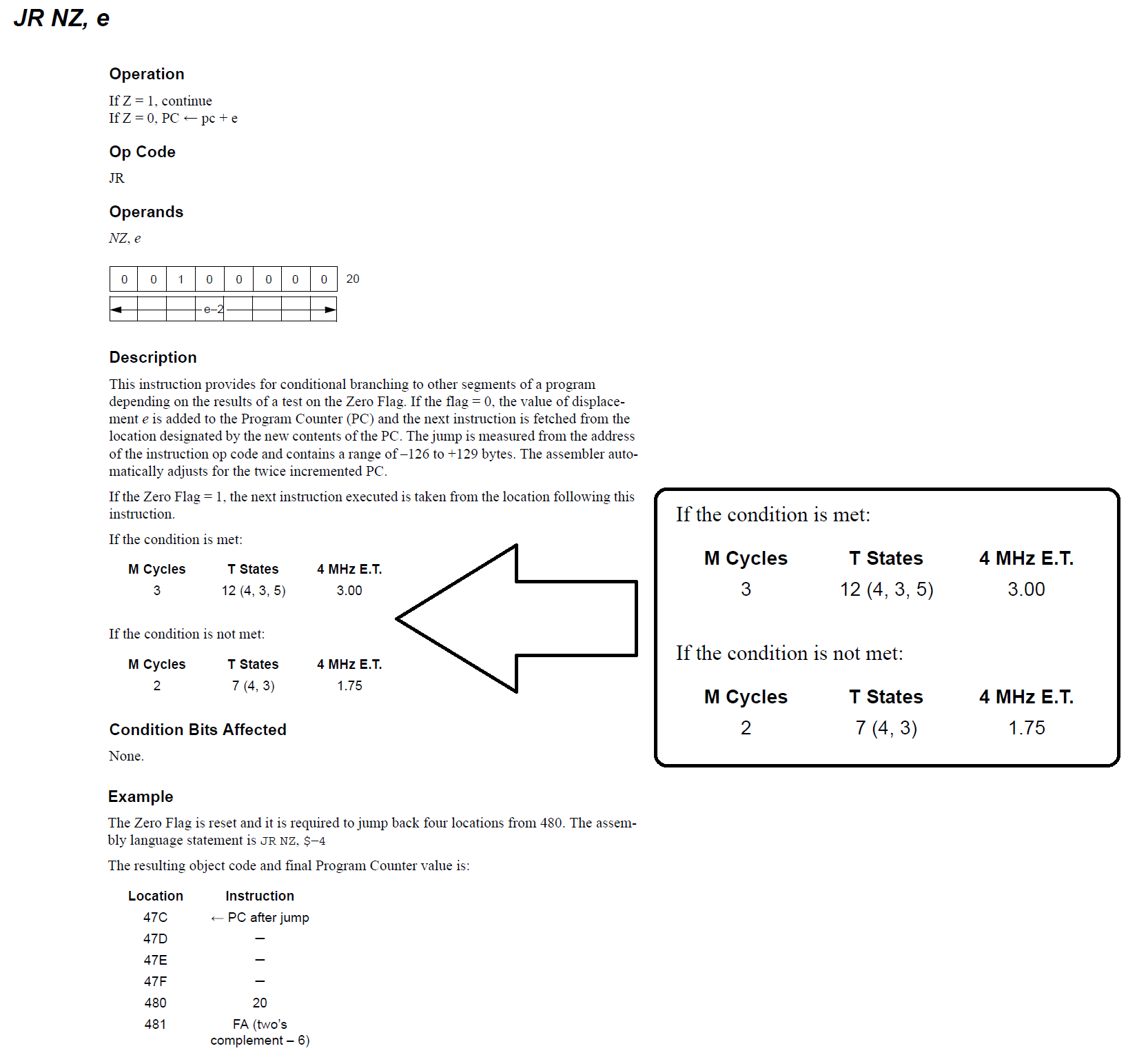
So, we can see that if the Zero Flag is not set, then the JR instruction can take up 12 T-States to complete, which is an age in process terms.
If we look at the code in this area, we can see that this instruction is executed every single time we write a byte to the screen memory. We know that our Sprite is 16 bytes by 32 lines, some simple maths tells us that this instruction is executed 512 times to display our little sprite.
Carrying this further, we know that every other time it’s executed, it will take 7 T-States (when the Zero flag is set and we don’t need to jump), and the rest will be 12 T-States (when the Zero Flag isn’t set and we perform a jump), so the total time just for this instruction is (256 * 7) + (256 * 12) = 3,072 T-States!
Now, a T-State for the SAM Coupé can be worked out as 1 Second / 6Mhz (clock speed) = 0.16µs (ish). So, our set of JR instructions above takes roughly 490µs… An AGE!
It should be noted however, that this is actually a best case estimation… Memory Contention, screen updates and rounding will actually mean that, in Screen Modes 3 and 4, it’s likely this figure will be 10-20% slower even.
Our code above has a couple of loops containing jumps… We’re looping around in a way which allows us to read 32 lines x 16 bytes of our sprite. If we’re looking to increase the efficiency of our code, we need to reduce the number of instructions which consume a lot of processor time, this would include of course the jumps we have.
Quite often when programming in assembly, writing less code and more loops is less efficient than writing more repetitive code but less loops. With this in mind.. We can rework our code with less loops;
;
; -----------------------------------------------------------------------------------
; |                                                                                 |
; | Program:    SAM Coupe Sprites Tutorial 3                                        |
; | Filename:   Sprites3.asm                                                        |
; | Version:    1.1                                                                 |
; | Date:       12/10/2017                                                          |
; | Author:     Pete Gallagher - PJG Creations Ltd                                  |
; |                                                                                 |
; -----------------------------------------------------------------------------------
;
		ORG 	0x8000		; Store the program in User Address Space
                DUMP	1,0             ;
                autoexec		; Automatically Execute the Program
;
; ***********************************************************************************
; *                                                                                 *
; *                                    Equates                                      *
; *                                                                                 *
; ***********************************************************************************
;
LMPR:           EQU     250             ; The Lower Memory Page Register Address
HMPR:           EQU     251             ; The Higher Memory Page Register Address
VMPR:           EQU     252             ; The Video Memory Page Register Address
JCLSBL:         EQU     334             ; The Clear Screen Routine...
                                        ; ... Set A to 0 to clear the whole screen) (0x14E)
JREADKEY:       EQU     361             ; The Keyboard Read Routine...
                                        ; ... Returns with Z Flag set if no key pressed...
                                        ; ... Otherwise A = Keycode for key pressed
;
; ***********************************************************************************
; *                                                                                 *
; *                                Application Start                                *
; *                                                                                 *
; ***********************************************************************************
;
                DI                      ; Disable Interupts
;
; Becuase the Stack Pointer lives in Page B, but we're paging the Screen into Pages A and B,
; we need to make sure we save the current Stack Pointer location, and create our own location.
; We rewrite our program here effectively, by storing it's original location in a holding position.
;
                LD	(System_SP+1),SP; Get the Current Stack Pointer Location and Overwrite...
                                        ; ... the holding value below.
;
; Get the Current Screen Page and set the LMPR register up so we can write to the screen
;
                IN      A,(VMPR)        ; Get the VMPR Register, which holds info about...
                                        ; ... which Page the Screen is Paged Into
                AND     0b00011110      ; We're only interested in the Screen Page...
                                        ; ... so mask off everything but the Page Bits...
                                        ; ... The result will be stored in the A Register
                OR      0b00100000      ; Set Bit 5 which, when loaded into the LMPR register...
                                        ; ... will Set the RAM in Page 0
                LD	(Scr_Page+1),A  ; Overwrite the holding value for the Screen Page location...
                                        ; ... now that we know it
;
                CALL    Clear_Screen    ; Clear the Screen
;
                LD	SP,0xC000       ; Set the Stack Pointer to a location of our choosing
;
                LD	A,(Scr_Page+1)  ; Get the current Screen Location which we stored earlier
                OR      0b00100000      ; Set Bit 5 which, when loaded into the LMPR register...
                                        ; ... will Set the RAM in Page 0
                OUT     (LMPR),A        ;
;
; All of the above shifting around of the Stack Pointer, allows us to Call routines...
; ... Which of course will store their return location on the Stack Pointer...
; ... This would've overwritten some of the Screen Page if left unreseolved...
;
;                CALL    Wait_For_Key   ; Wait for a keypress
;
; Print a sprite in the top left corner
;
                LD      DE,0x0000       ; Point to the Top Left corner of our screen
;
; Print a Sprite
;
print_sprite:	LD 	HL,Sprite1_1    ; Set pointer to start of our Sprite
                LD 	BC,512		; Set up loop counter, 16 bytes per Row of a sprite to print
;
		JP	Print_Loop1	; We must skip the first increment here so that we start at 0
;
; This is the start of our Sprite Printing Loop
;
Print_Loop:	LD      A,E             ;
                ADD     112             ;
                LD      E,A             ;
                INC     D               ; Set for the Next Row taking account of our x position
;
; Print the Even Row of the Sprite
;
Print_Loop1:    FOR     16, LDI		; This is a PYZ80 directive which inserts 16 LDI instructions
;
                LD      A,E             ;
                ADD     112             ;
                LD      E,A             ; Set for the Next Row taking account of our x position
;
; Print the Odd Row of the Sprite
;
                FOR     16, LDI		; This is a PYZ80 directive which inserts 16 LDI instructions
;
; LDI Moves the Value at the location pointed to by (HL)...
; ... into the location pointed to by (DE)...
; ... It then Decrements BC, setting P/V (Parity / Overflow) flag if the BC has reached zero
;
                JP      PE, Print_Loop  ; Loop until BC = zero (i.e. P/V set)
;
                CALL    Wait_For_Key    ;
;
;
; We must remember to switch BASIC back into Page 0
;
                LD      A,0x1F          ; Set ROM0 back into Page A...
                OUT     (LMPR), A       ; ... So that when we try to return to BASIC it all still works!
;
; Return the System Stack Pointer to it's original location in Bank B somewhere...
;
System_SP:	LD   	SP,0            ; Place holder for the System Stack Location...
                                        ; This will be overwritten above once we know it's location
                EI                      ; Enable Interupts
;
; Return back to BASIC
;
                RET                     ;
;
; ***********************************************************************************
; *                                                                                 *
; *                                Clear the Screen                                 *
; *                                                                                 *
; ***********************************************************************************
;
Clear_Screen:   XOR     A               ; Clear the A register, so when passed into clear screen...
                                        ; ...it clears the whole screen
                CALL    JCLSBL          ; Clear the Screen
                DI                      ; Disable Interupts
                RET                     ;
;
; ***********************************************************************************
; *                                                                                 *
; *                                Wait for a KeyPres                               *
; *                                                                                 *
; ***********************************************************************************
;
Wait_For_Key:   PUSH    BC              ; Save the BC Registers
                PUSH    DE              ; Save the DE Registers
                PUSH    HL              ; Save the HL Registers
                LD	A,0x1F          ; Set for ROM in Page A
                OUT 	(LMPR),A        ;
;
Key_Loop:       CALL	JREADKEY	; Read the Keyboard (Zero if no key)
       		JR 	Z,Key_Loop      ; If no key pressed, then loop
;
No_Key_Loop:    CALL	JREADKEY	; Read the Keyboard (Zero if no key)
       		JR 	NZ,No_Key_Loop  ; If key still pressed, then loop
;
                DI                      ; Disable Interuprts
;
Scr_Page:	LD      A,0	        ; Place holder for the Screen Page...
                                        ; ...The 0 will be overwritten above once we know where it is...
                OUT	(LMPR),A        ; Page the Screen into the relevant Page
                POP     HL              ; Retrieve the HL Registers
                POP     DE              ; Retrieve the DE Registers
                POP     BC              ; Retrieve the BC Registers
                RET                     ;
;
; ***********************************************************************************
; *                                                                                 *
; *                                     Sprites                                     *
; *                                                                                 *
; ***********************************************************************************
;
Sprite1_1:      DEFB      0xFF, 0xFF, 0xFF, 0xFF, 0xFF, 0xFF, 0xFF, 0xFF, 0xFF, 0xFF, 0xFF, 0xFF, 0xFF, 0xFF, 0xFF, 0xFF
Sprite1_2:      DEFB      0xF4, 0x44, 0x44, 0x44, 0x44, 0x44, 0x44, 0x44, 0x44, 0x44, 0x44, 0x44, 0x44, 0x44, 0x44, 0x4F
Sprite1_3:      DEFB      0xF4, 0x44, 0x44, 0x44, 0x44, 0x44, 0x44, 0x44, 0x44, 0x44, 0x44, 0x44, 0x44, 0x44, 0x44, 0x4F
Sprite1_4:      DEFB      0xF4, 0x44, 0x44, 0x44, 0x44, 0x44, 0x44, 0x44, 0x44, 0x44, 0x44, 0x44, 0x44, 0x44, 0x44, 0x4F
Sprite1_5:      DEFB      0xF4, 0x44, 0x44, 0x44, 0x44, 0x44, 0x44, 0x44, 0x44, 0x44, 0x44, 0x44, 0x44, 0x44, 0x44, 0x4F
Sprite1_6:      DEFB      0xF4, 0x44, 0x44, 0x44, 0x44, 0x44, 0x44, 0x44, 0x44, 0x44, 0x44, 0x44, 0x44, 0x44, 0x44, 0x4F
Sprite1_7:      DEFB      0xF4, 0x44, 0x44, 0x44, 0x44, 0x44, 0x44, 0x44, 0x44, 0x44, 0x44, 0x44, 0x44, 0x44, 0x44, 0x4F
Sprite1_8:      DEFB      0xF4, 0x44, 0x44, 0x44, 0x44, 0x44, 0x44, 0x44, 0x44, 0x44, 0x44, 0x44, 0x44, 0x44, 0x44, 0x4F
Sprite1_9:      DEFB      0xF4, 0x44, 0x44, 0x44, 0x44, 0x44, 0x44, 0x44, 0x44, 0x44, 0x44, 0x44, 0x44, 0x44, 0x44, 0x4F
Sprite1_10:     DEFB      0xF4, 0x44, 0x44, 0x44, 0x44, 0x44, 0x44, 0x44, 0x44, 0x44, 0x44, 0x44, 0x44, 0x44, 0x44, 0x4F
Sprite1_11:     DEFB      0xF4, 0x44, 0x44, 0x44, 0x44, 0x44, 0x44, 0x44, 0x44, 0x44, 0x44, 0x44, 0x44, 0x44, 0x44, 0x4F
Sprite1_12:     DEFB      0xF4, 0x44, 0x44, 0x44, 0x44, 0x44, 0x44, 0x44, 0x44, 0x44, 0x44, 0x44, 0x44, 0x44, 0x44, 0x4F
Sprite1_13:     DEFB      0xF4, 0x44, 0x44, 0x44, 0x44, 0x44, 0x44, 0x44, 0x44, 0x44, 0x44, 0x44, 0x44, 0x44, 0x44, 0x4F
Sprite1_14:     DEFB      0xF4, 0x44, 0x44, 0x44, 0x44, 0x44, 0x44, 0x44, 0x44, 0x44, 0x44, 0x44, 0x44, 0x44, 0x44, 0x4F
Sprite1_15:     DEFB      0xF4, 0x44, 0x44, 0x44, 0x44, 0x44, 0x44, 0x44, 0x44, 0x44, 0x44, 0x44, 0x44, 0x44, 0x44, 0x4F
Sprite1_16:     DEFB      0xF4, 0x44, 0x44, 0x44, 0x44, 0x44, 0x44, 0x44, 0x44, 0x44, 0x44, 0x44, 0x44, 0x44, 0x44, 0x4F
Sprite1_17:     DEFB      0xF4, 0x44, 0x44, 0x44, 0x44, 0x44, 0x44, 0x44, 0x44, 0x44, 0x44, 0x44, 0x44, 0x44, 0x44, 0x4F
Sprite1_18:     DEFB      0xF4, 0x44, 0x44, 0x44, 0x44, 0x44, 0x44, 0x44, 0x44, 0x44, 0x44, 0x44, 0x44, 0x44, 0x44, 0x4F
Sprite1_19:     DEFB      0xF4, 0x44, 0x44, 0x44, 0x44, 0x44, 0x44, 0x44, 0x44, 0x44, 0x44, 0x44, 0x44, 0x44, 0x44, 0x4F
Sprite1_20:     DEFB      0xF4, 0x44, 0x44, 0x44, 0x44, 0x44, 0x44, 0x44, 0x44, 0x44, 0x44, 0x44, 0x44, 0x44, 0x44, 0x4F
Sprite1_21:     DEFB      0xF4, 0x44, 0x44, 0x44, 0x44, 0x44, 0x44, 0x44, 0x44, 0x44, 0x44, 0x44, 0x44, 0x44, 0x44, 0x4F
Sprite1_22:     DEFB      0xF4, 0x44, 0x44, 0x44, 0x44, 0x44, 0x44, 0x44, 0x44, 0x44, 0x44, 0x44, 0x44, 0x44, 0x44, 0x4F
Sprite1_23:     DEFB      0xF4, 0x44, 0x44, 0x44, 0x44, 0x44, 0x44, 0x44, 0x44, 0x44, 0x44, 0x44, 0x44, 0x44, 0x44, 0x4F
Sprite1_24:     DEFB      0xF4, 0x44, 0x44, 0x44, 0x44, 0x44, 0x44, 0x44, 0x44, 0x44, 0x44, 0x44, 0x44, 0x44, 0x44, 0x4F
Sprite1_25:     DEFB      0xF4, 0x44, 0x44, 0x44, 0x44, 0x44, 0x44, 0x44, 0x44, 0x44, 0x44, 0x44, 0x44, 0x44, 0x44, 0x4F
Sprite1_26:     DEFB      0xF4, 0x44, 0x44, 0x44, 0x44, 0x44, 0x44, 0x44, 0x44, 0x44, 0x44, 0x44, 0x44, 0x44, 0x44, 0x4F
Sprite1_27:     DEFB      0xF4, 0x44, 0x44, 0x44, 0x44, 0x44, 0x44, 0x44, 0x44, 0x44, 0x44, 0x44, 0x44, 0x44, 0x44, 0x4F
Sprite1_28:     DEFB      0xF4, 0x44, 0x44, 0x44, 0x44, 0x44, 0x44, 0x44, 0x44, 0x44, 0x44, 0x44, 0x44, 0x44, 0x44, 0x4F
Sprite1_29:     DEFB      0xF4, 0x44, 0x44, 0x44, 0x44, 0x44, 0x44, 0x44, 0x44, 0x44, 0x44, 0x44, 0x44, 0x44, 0x44, 0x4F
Sprite1_30:     DEFB      0xF4, 0x44, 0x44, 0x44, 0x44, 0x44, 0x44, 0x44, 0x44, 0x44, 0x44, 0x44, 0x44, 0x44, 0x44, 0x4F
Sprite1_31:     DEFB      0xF4, 0x44, 0x44, 0x44, 0x44, 0x44, 0x44, 0x44, 0x44, 0x44, 0x44, 0x44, 0x44, 0x44, 0x44, 0x4F
Sprite1_32:     DEFB      0xFF, 0xFF, 0xFF, 0xFF, 0xFF, 0xFF, 0xFF, 0xFF, 0xFF, 0xFF, 0xFF, 0xFF, 0xFF, 0xFF, 0xFF, 0xFF
An Even More Advanced Square Sprite
Sometimes, More is Less
Once again, here’s a flow chart of how our new program is working;
You’ll see that, for the most part, our setup section is practically identical to the previous version of code; Define Equates, Move the Stack, Move the RAM and ROM, Point to our Sprite etc.
You’ll quickly see that we only have one loop now, instead of two loops, where one loop was nested inside another.
When we get to line 81 we start to get into where the differences appear;
LD BC,512Where we’re setting a counter up to count to 512. You may remember that we have 512 bytes in our Sprite – 16 bytes (2 per pixel) x 32 Lines, so our new single loop will be counting down per byte instead of per byte and per line.
Skipping the section on Lines 87 to 90, for now, we’ll see something new on Line 94;
FOR 16, LDIThis line introduces two new concepts at once… The FOR instruction is what’s known as an Assembler Directive, and is a way to be able to tell PYZ80 that we want to create a sequential list of Instructions. The 16 figure tells PYZ80 to create 16 LDI instructions in a row, and just minimises that amount of code shown in our source file, but in reality, we really do have 16 LDI instructions in a row.
The second concept we have is the LDI Instruction itself, which is a relatively complex instruction as it performs quite a few functions together. The Z80 datasheet details LDI as the following;
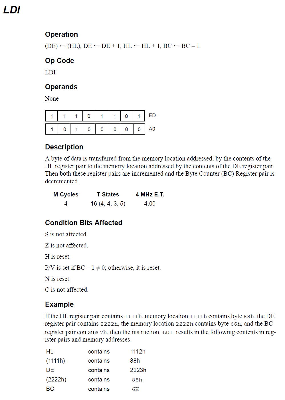
In simple terms, the LDI instruction, copies data from the location pointed to by the HL register pair into the location pointed to by the DE register. Once it’s finished copying the data, it increments HL and DE, and finally decrements the BC register.
If you look back at our previous version of code, you’ll see we were already performing exactly this sequence of events ourselves, but instead of using one single instruction, we were using a bunch of more instructions including INC and a complicated subtract process.
Then, on lines 96 to 98 we have the following;
LD A,E
ADD 112LD E,A
What we achieve here is to move the screen memory location we’re pointing to straight onto the line below, directly below the leftmost pixel on the line above. Whereas in our previous version of code, we tested the line counter Bit 0 to determine if we were on an odd line or not, we now simply print two lines at one time – The Odd and Even lines. So on line 102, we have an other identical FOR Directive to create 16 LDI instructions.
On line 108 we have the end of our only loop;
JP PE, Print_LoopWhen the LDI decrements the BC register, if the BC register reaches Zero it clears the Parity Bit, letting us know that our loop has completed. If the Parity Bit is set, then we carry on looping back up to line 87, where we set our screen memory location to the next line again.
Onward from that, once our loop is completed, we perform the same functions as previously, waiting for a key, returning the stack and the ROM and re-enabling interrupts, before returning to BASIC.
As always, you can download a copy of the program as a disk image here.
An Even More Advanced Square Sprite
Why, More is Less
Ok, so it might seem counter intuitive, we’ve replaced less code with more code and somehow it’s quicker? Quicker… Yes, more efficient… Yes, easier to read… Most certainly!
The 32 LDI instructions have effectively replaced over 20 of our previous instructions, and the way we’ve done it has dropped our jumps from 3 to 1.
Taking a second look at the timings for LDI instruction;
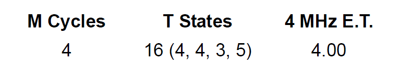
We can see that the instruction uses 16 T-States to perform all of it’s operations, and we have 32 of them per row, so we have 512 T-States per row.. We have 32 rows, so we have 16,384 T-States for the whole Sprite. However, we’re now only jumping once, where as in the previous example we were jumping a whole heap more;
16 times per row to the Odd / Even Line Code, 16 times per row back from the Odd / Even Line Code, 32 times per row to return to the start of the row and print our next row of pixels. Combine that with all the other instructions which we’ve done away with, and you start to get the idea about how we can save a good deal of processor time by writing our code in this way.
We can actually see the real life difference between the two versions of code by running them in SimCoupe and comparing the T-Diff figures for both. If we insert a break point at the beginning of both versions of code, and another one at our final call to the Wait_For_Key routine, SimCoupe will show us the number of T-Cycles which have elapsed since the last time the debug window was shown. We’ll be shown the debug window when our code first starts, with the code stopping at our first breakpoint at address 0x8000. closing the debugger window will then allow our code to run on until it finishes drawing our sprite, and the code hits our final breakpoint at the call to the Wait_For_Key routine.
For Sprite 2, we have the following;
Which shows that 322,920 T-States have elapsed since the last time we were shown the debug window, basically how long it has taken for our routine to run to this point.
For our new version of code we have the following;
Which shows that only 280,024 T-Cycles have elapsed… A saving over 40,000 T-Cycles, which is a saving over over 5ms!!
Granted, this might not sound like a lot, but in processor terms, this is an absolutely massive saving. If you then consider that we could be running this routine many times per second if we wanted to animate our sprites, then the savings really start adding up, which could make the difference between a jerky animation and a nice smooth one, or a responsive game, or one which is laggy and slow to play.
In Conclusion
So, we’ve learnt quite a lot in this rather extended blog post! The highlights are;
- What sprites are
- How Sprites are created and what they look like from a programming perspective
- A little about the SAM Coupé Palette.
- The SAM Coupé screen modes and Screen Dimensions
- How the SAM Coupé reads and writes to it’s RAM, including Paging
- How the SAM Coupé deals with Screen Memory
- How we can create a really simple Sprite and display it on the screen
- How we can improve our code to display a full 32×32 pixel Sprite
- How we can improve the speed, efficiency and readability of our code using better instructions
I hope you’ve enjoyed this second tutorial. Please do check back again soon for more instalments!
